The first overhead starts to appear in June 2005.
The very first test runs with the wiring on the first board. A few snags needed to be ironed out, but generally good. A new chassis had to be built for the trolleybus, incorporating the Faller steering arm.
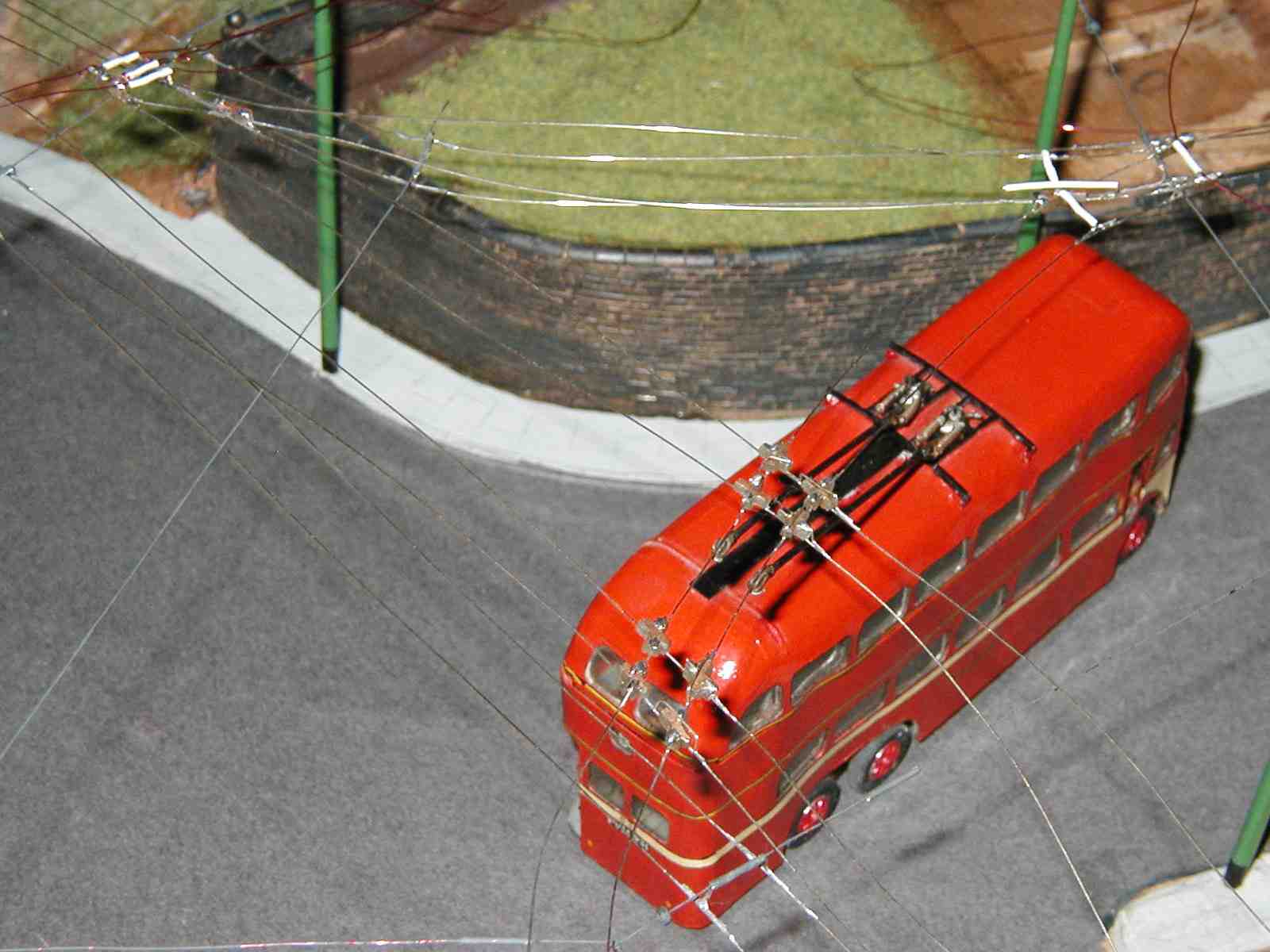
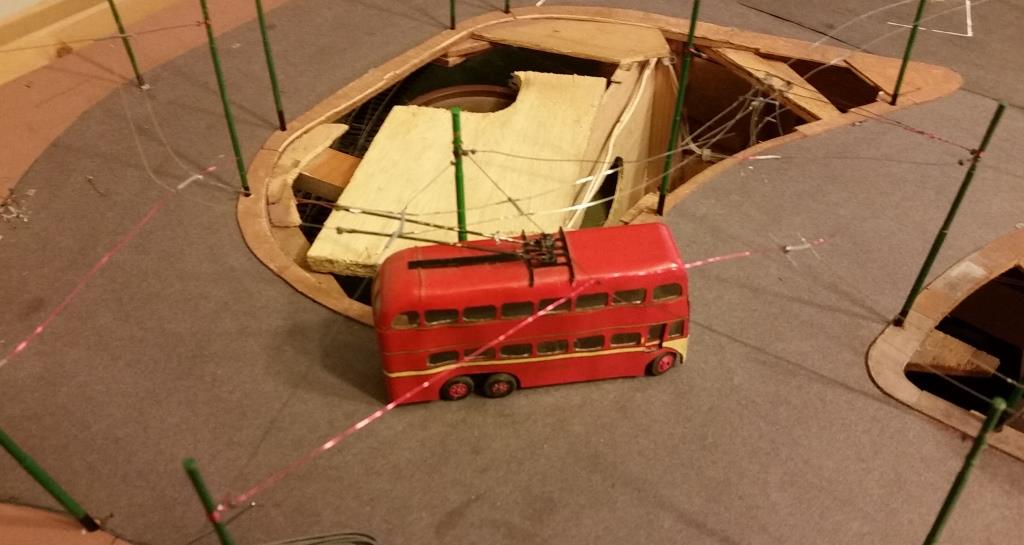
A closer view of the first board's overhead being tested.
Overhead now painted so it looks more the part (but the trolleybus wheels are not!). (>>)
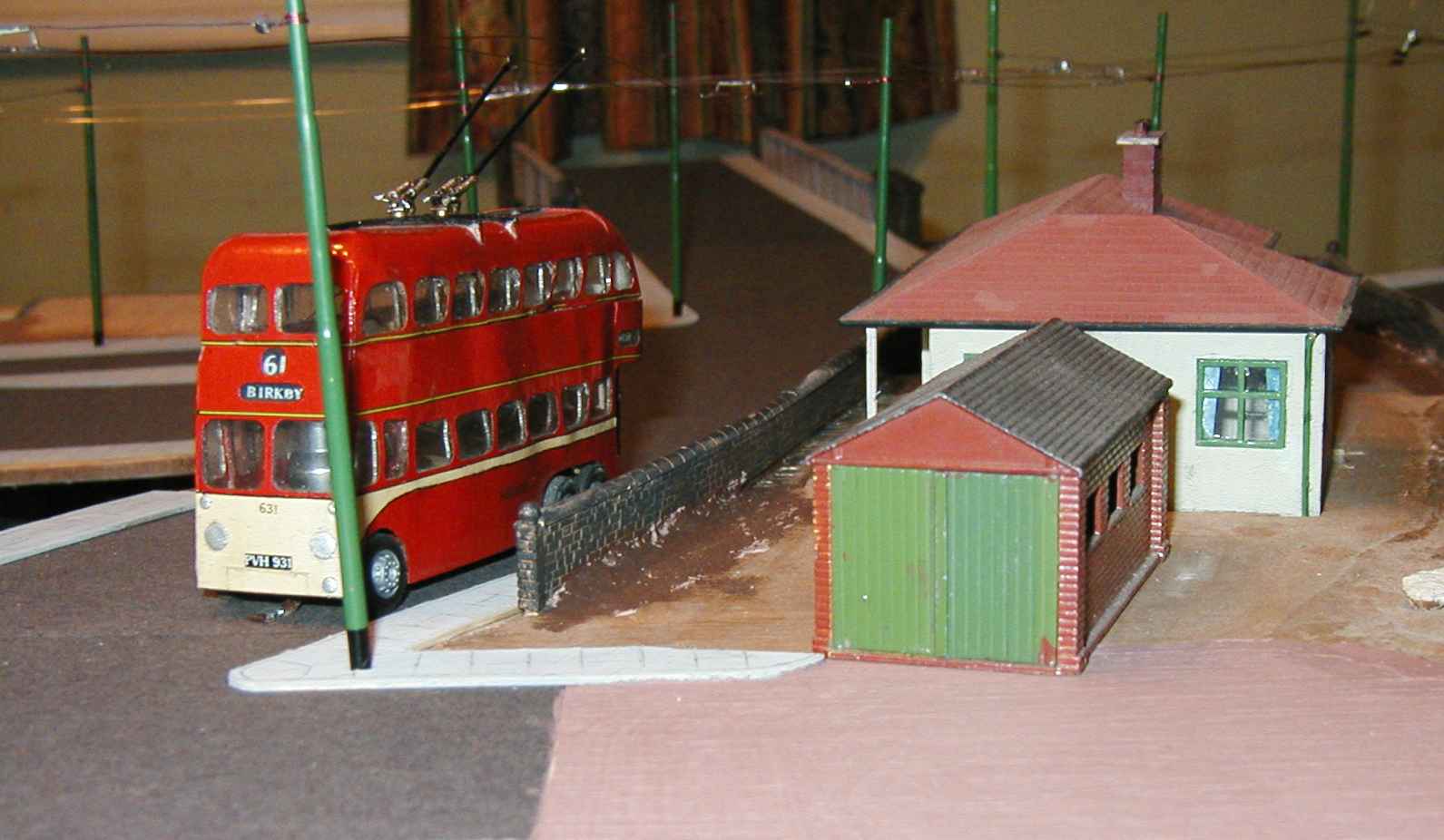
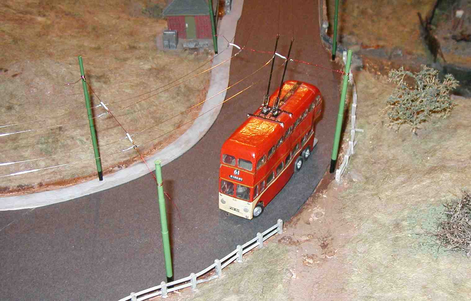
The second board gets its wires, and the trolleybus runs up the slope past the bungalow. A complete loop was erected in time for the Sheffield Exhibition in June 2005.
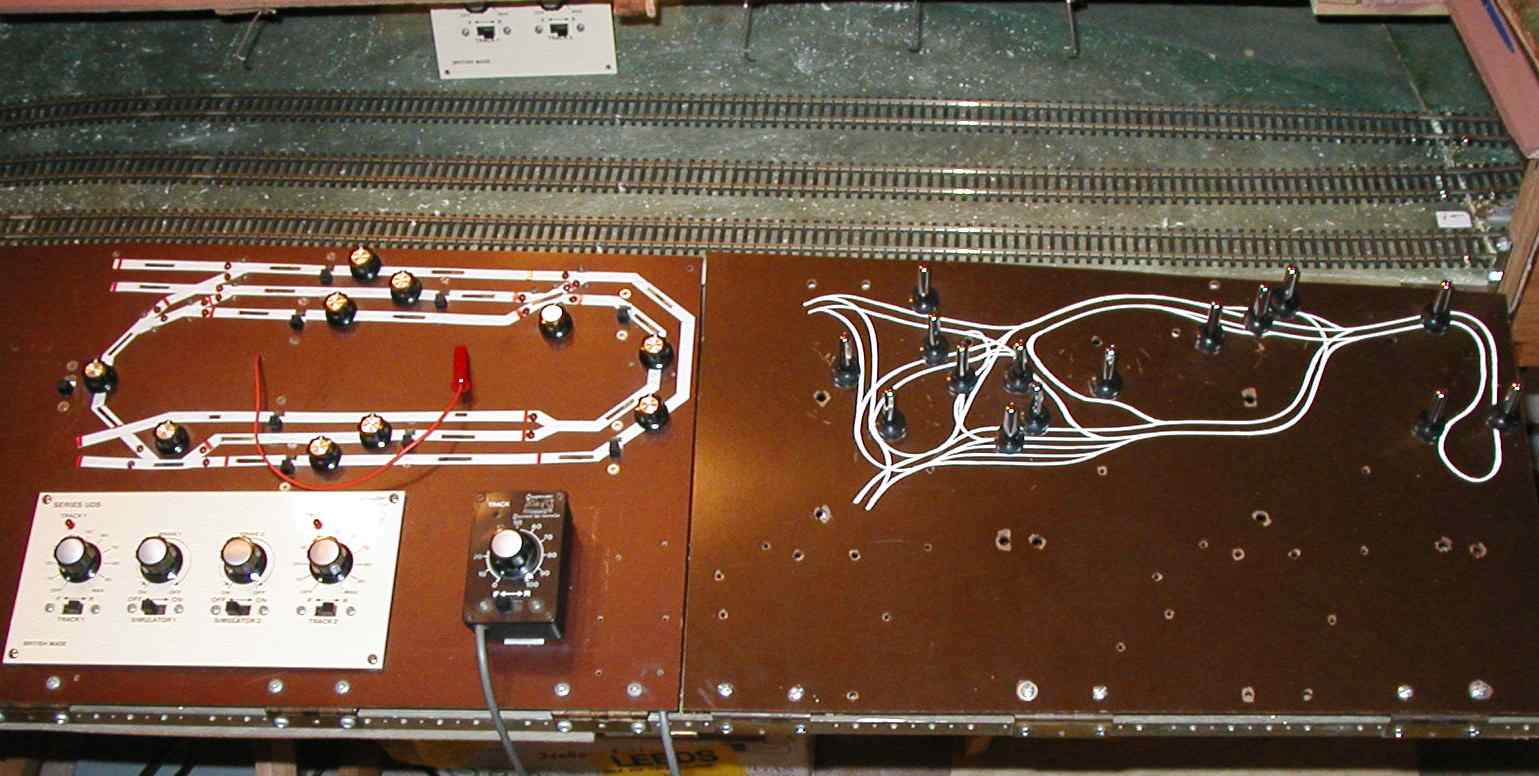 (>>)
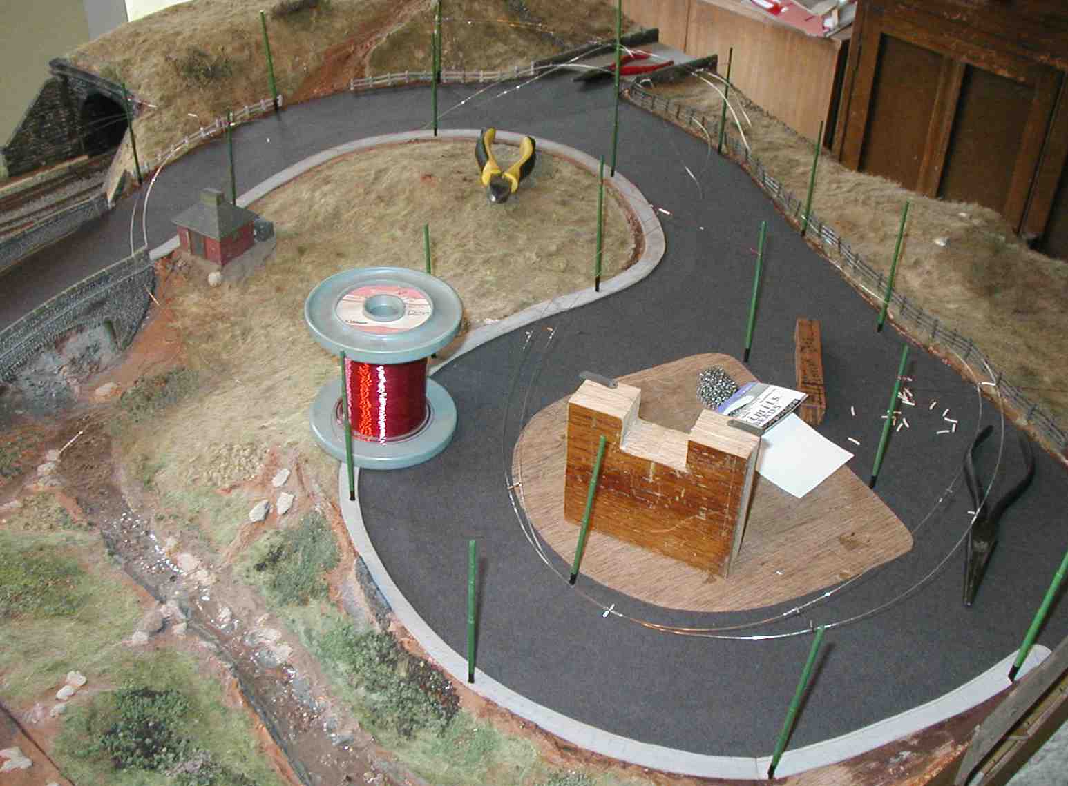
(>>)The control area has had a panel for the buses added. The switches are to activate the bus stops; the controller behind will be inserted into the bus panel for trolleybus control. Compare this with the third photo on the Early Days page.
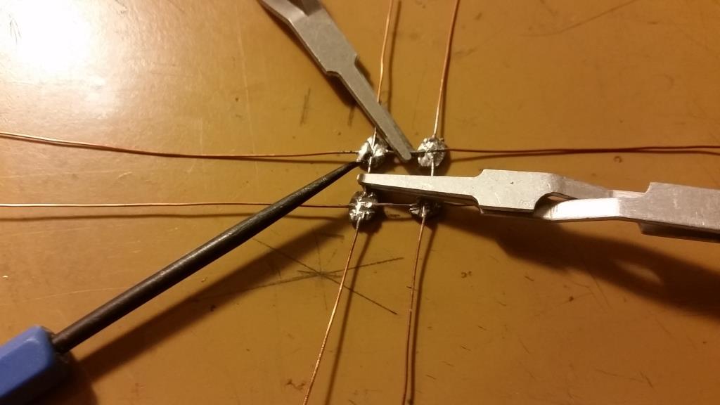
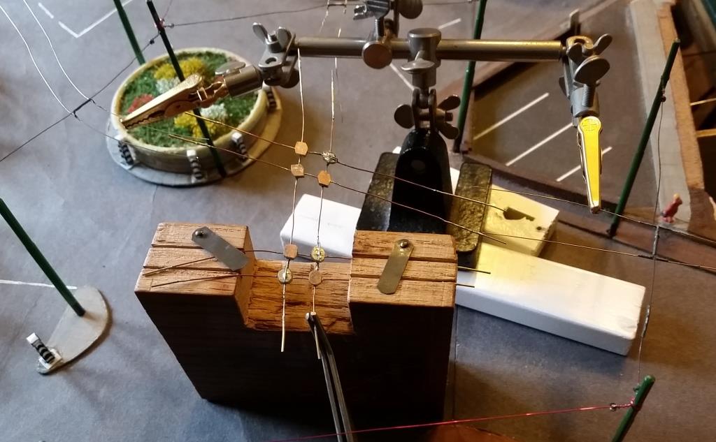
The new trolleybus short-working was added in 2007. Above is a prototype of a 60� crossing which worked well. Board 2 needed 4 of these, 4 x 75� and 3 x 25�, plus 4 facing and 2 trailing point blades. This made up two complete crossings and three complete frogs (points); that's before the ones required on Board 3. All the overhead I plan to install will take some time!
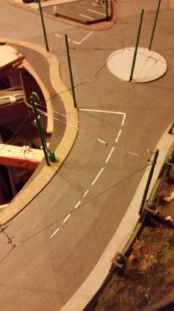
The two angled crossings completed and placed in approximate position over the existing overhead at the bottom of the slope on Board 2. The frogs were still to do at this time. (>>)
Two frogs completed - the facing for turning up the hill or going straight on, and the trailing one up the hill. The facing frog went through three versions before I got one to work! Only the other facing frog to pull into the station layby, and tidying up to do now, then the complete unit can be installed, replacing the existing wiring. (>>)
(>>)
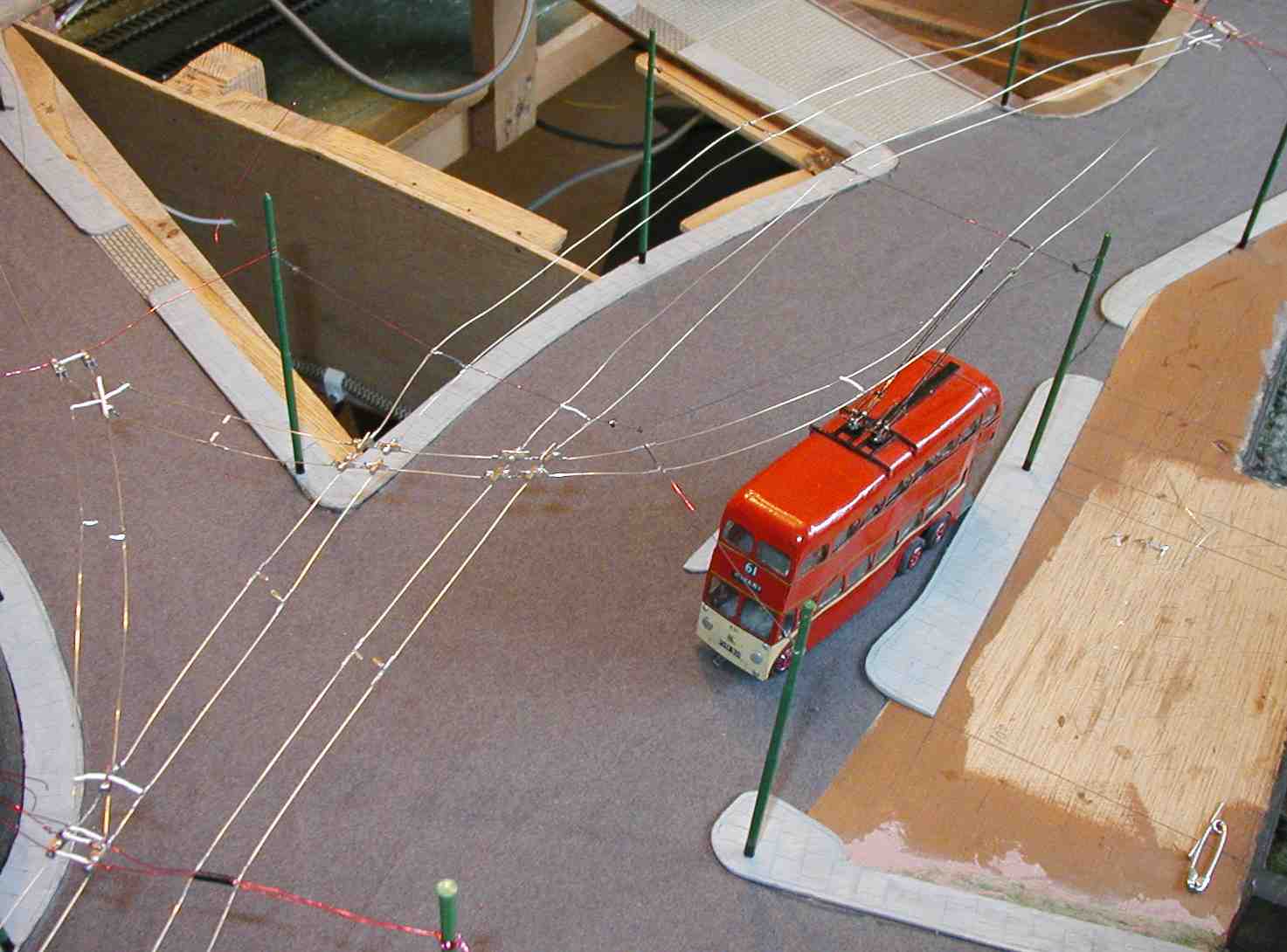
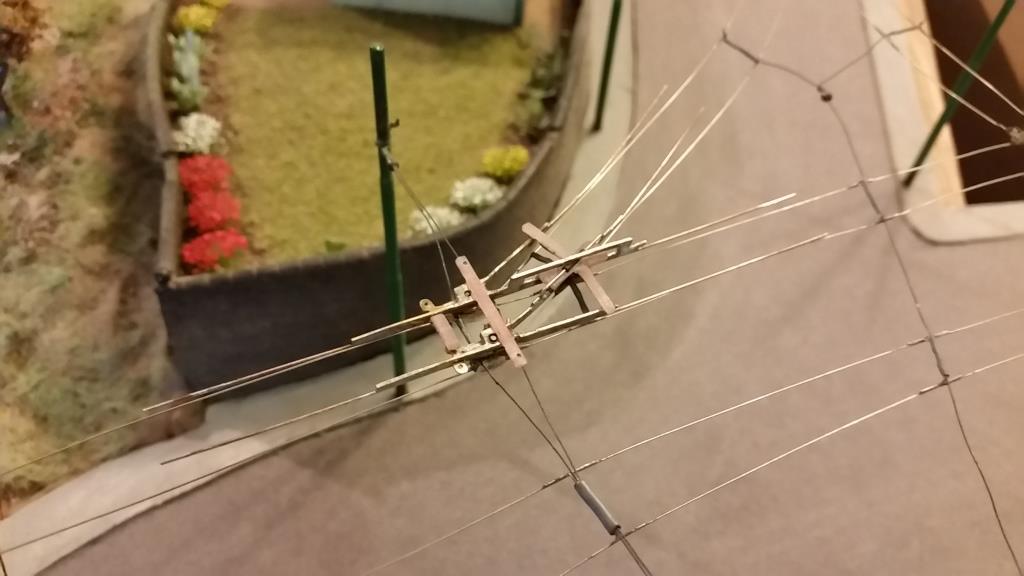
New module installed for test running. Some pull-offs not yet fitted, tensioning not finished and a few problems, but connected to the rest of the network and looking promising!
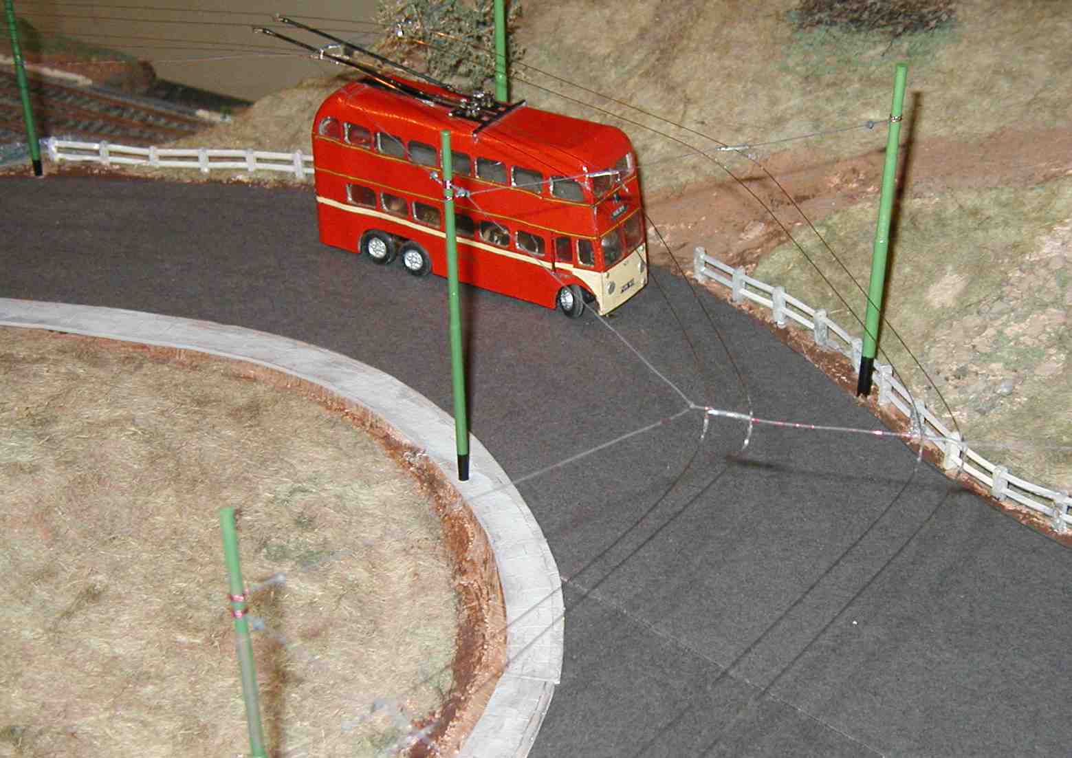
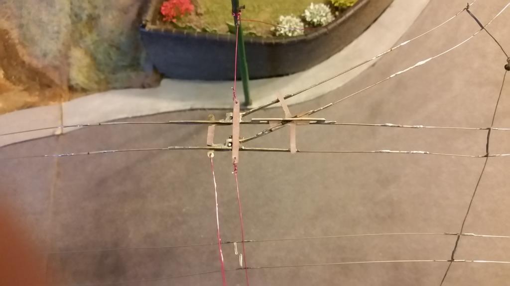
Closer view of the layby frog in place, and overview of the whole junction before all the pull-offs were added and final painting, on the right.
(>>)
 (>>)
(>>)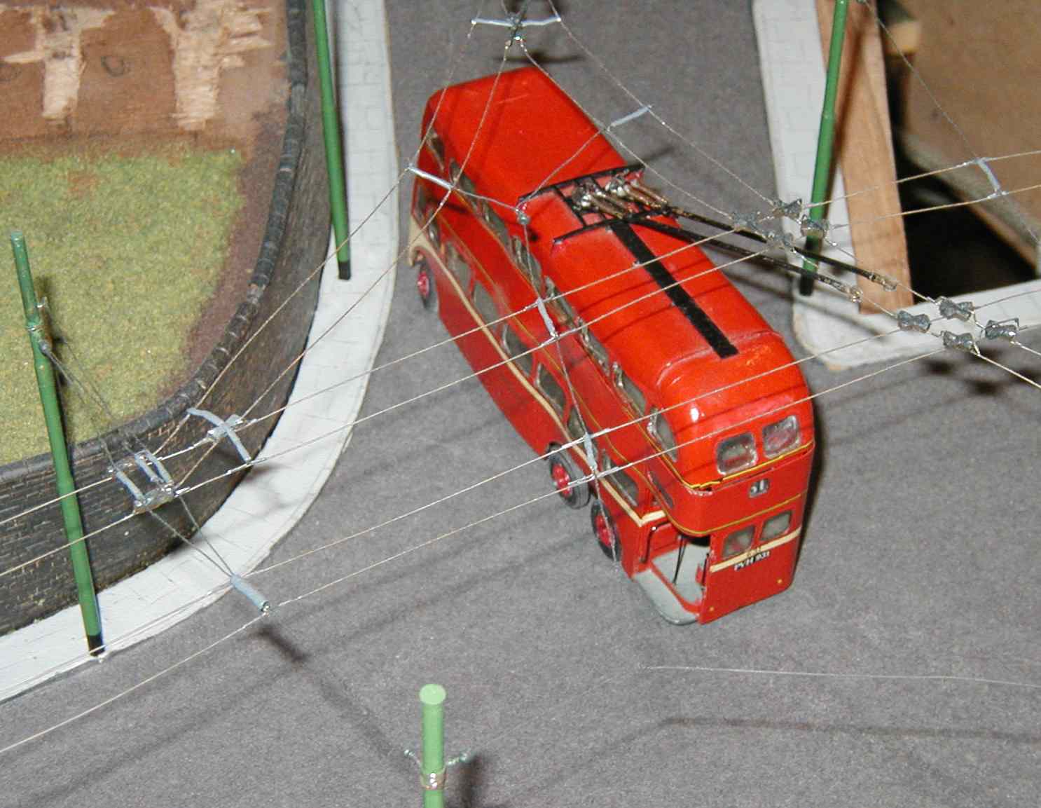
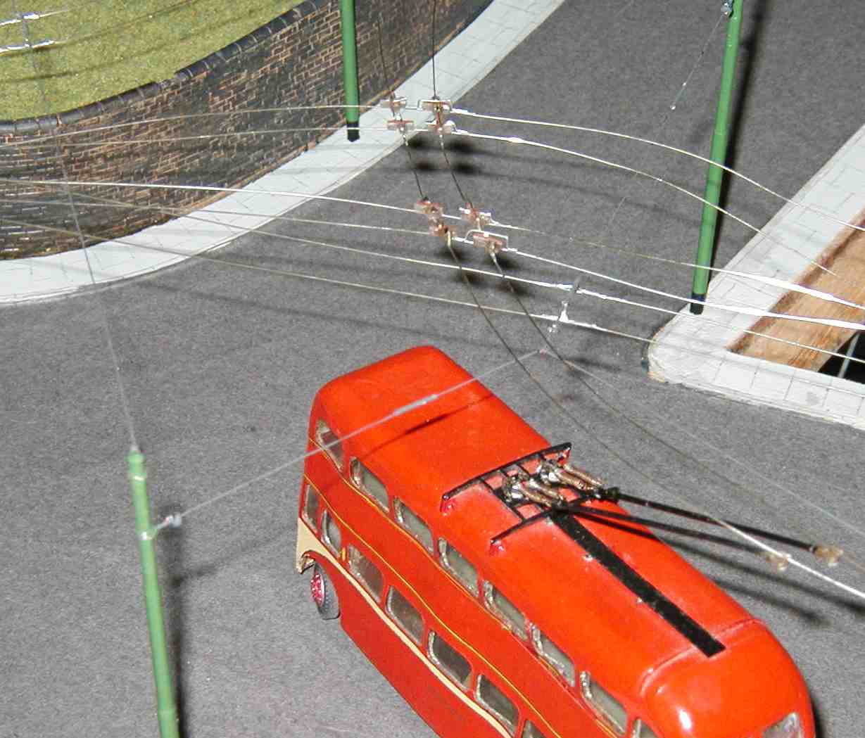
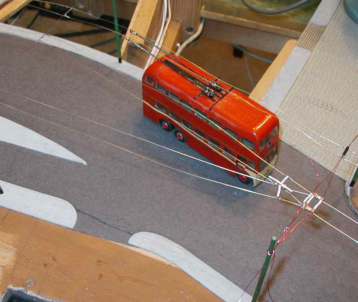
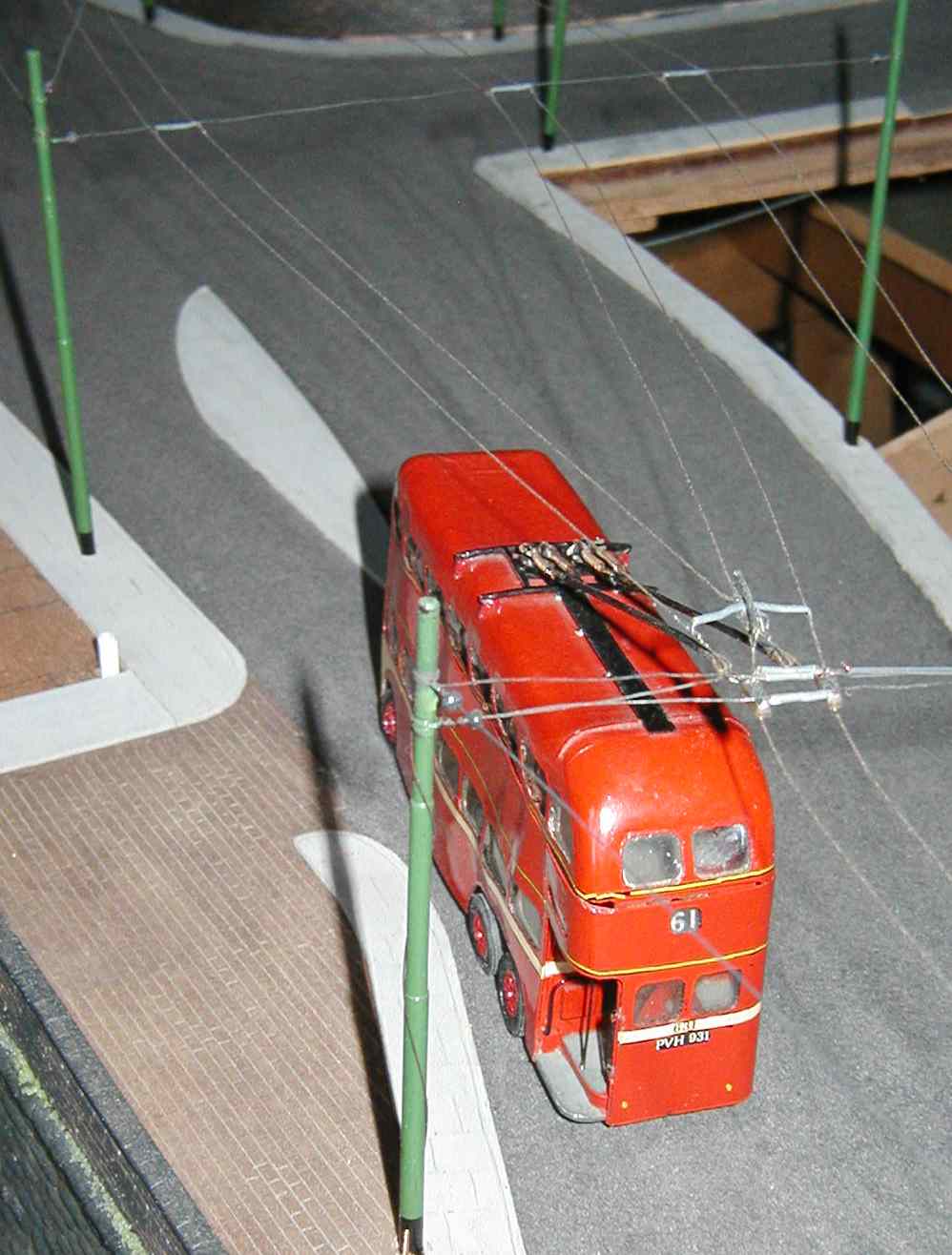
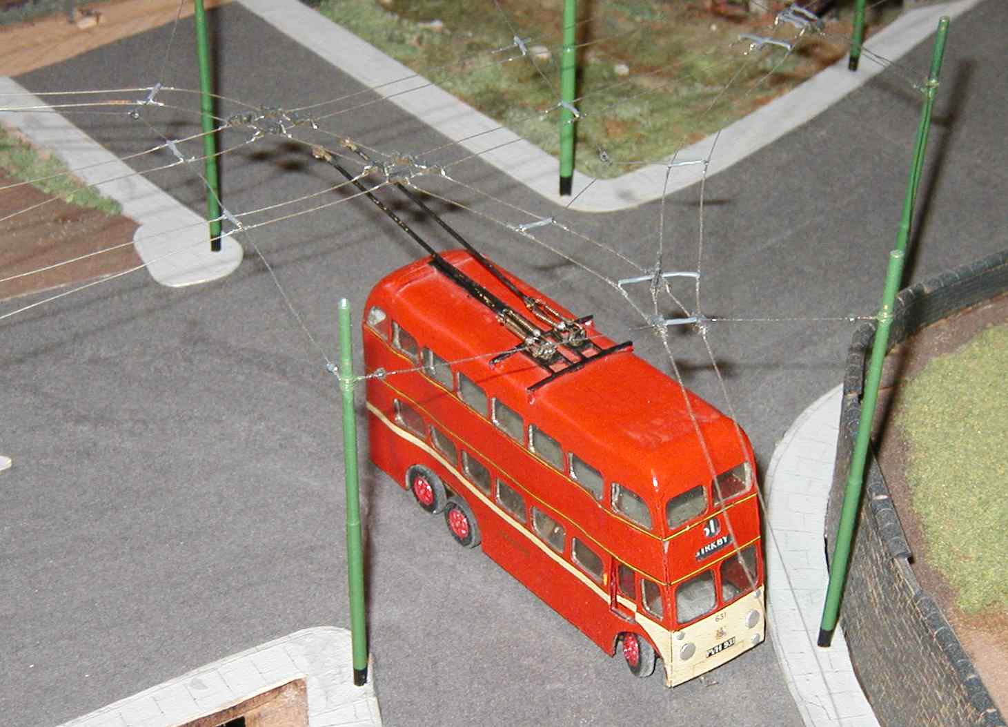
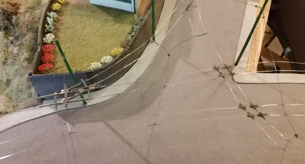
Three shots of the finished junction, with all the pull-offs in position and spacer bars painted.
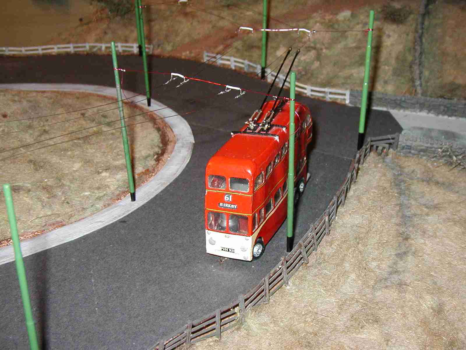
On the left: the trolleybus enters the loop in front of the station.
Above and right: swinging up the hill from the station loop.
(>>)
Operation of the frogs by pull wire has been OK, but leaves a bit to be desired. Instead of the sprung version I constructed, I plan to alter the frogs to 'pull both ways', ie. not sprung so they will need to be pulled in either direction. This will take some of the stresses off the overhead.
Alternatively, if the situation is suitable, they will be made so that the travel of the bus will pull the booms the right way. (>>)
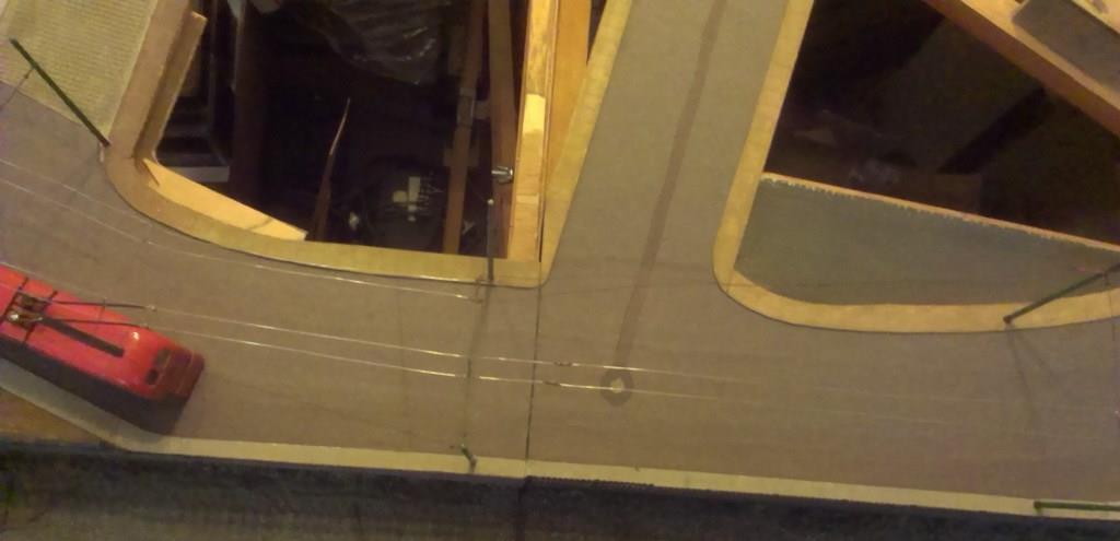
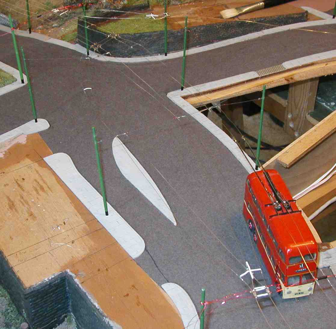
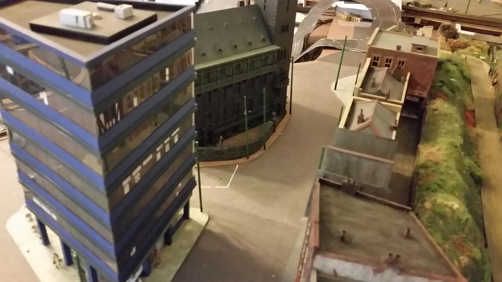
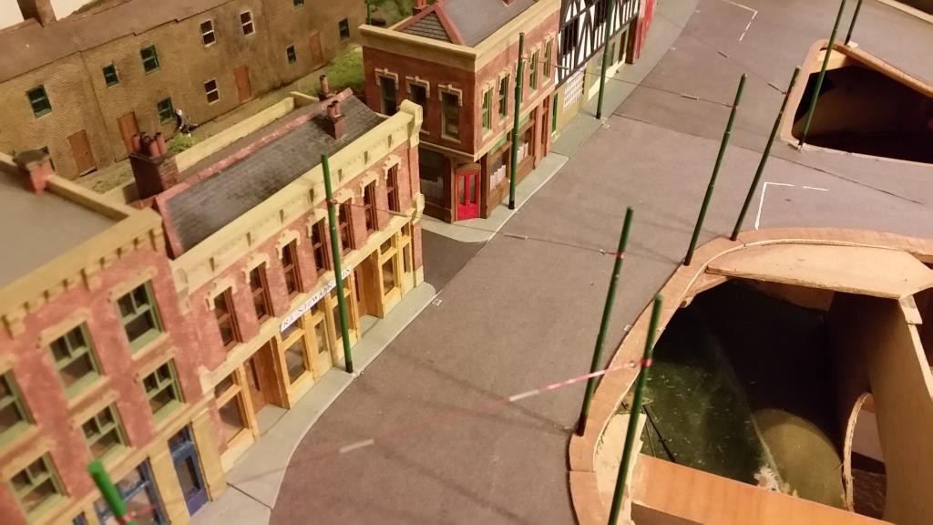
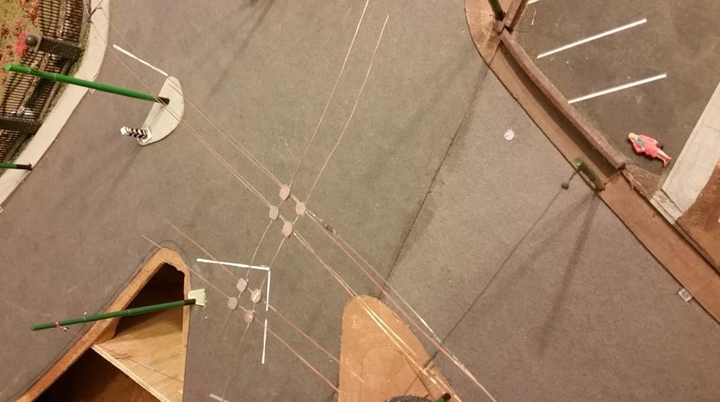
It wasn't obvious from previous photos that the wiring into town (towards the right) stopped at the point shown above. It was built to here as part of the new intersection at the station but not completed.
Every span wire along the route has already had a spacer bar inserted in readiness so that the span wires don't need to be re-strung. Some of these can be seen on the photo to the right. (>>)
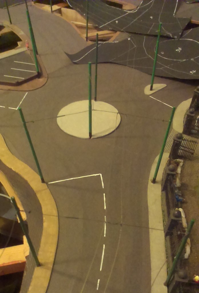
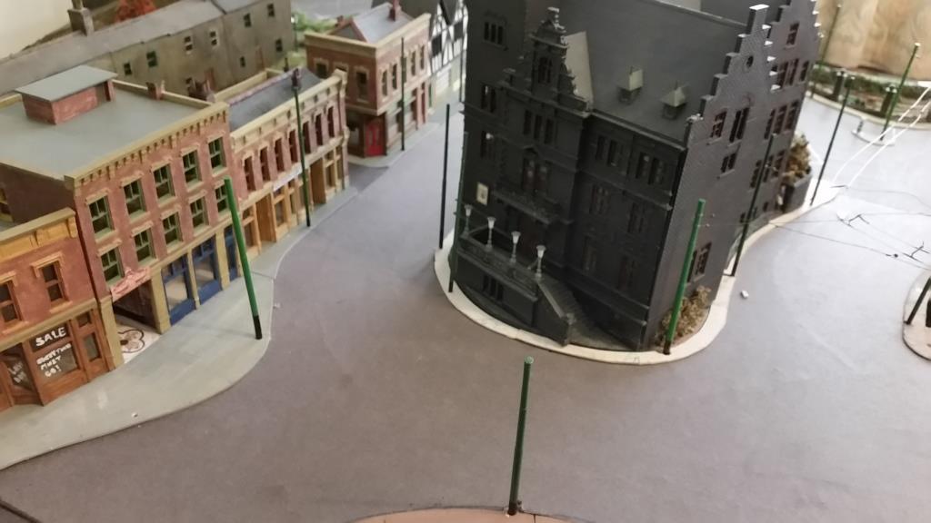
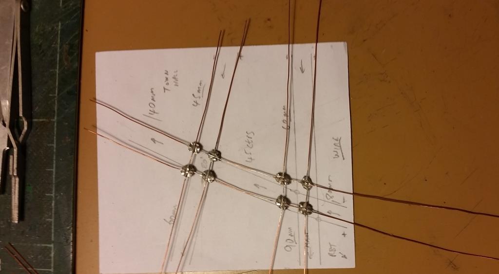
This is where the new wiring will go - up to the roundabout, then to the upper right, and then return round the back of the Town Hall. (>>)
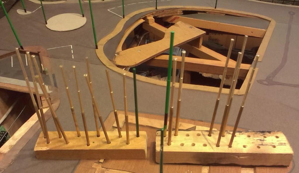
This is the forest of traction poles machined up on a lathe. There are different heights and also different diameters for different purposes. They now need painting like the two in the middle.
It is surprising how many poles are needed for a short length of wiring. However, many of them will be used again for later extensions to the overhead. (>>)
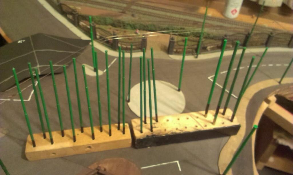
The forest of 19 poles finally painted and ready to be planted. I have some pavement work to do before that happens though.
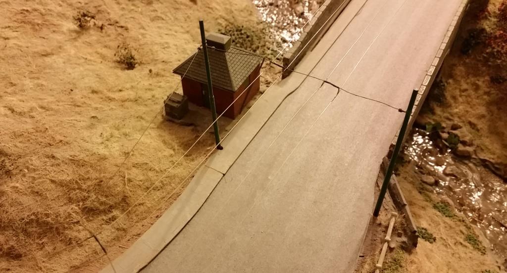
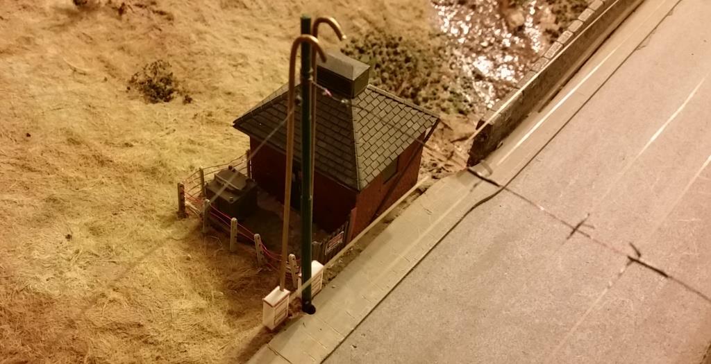
Before the extra wiring can be erected, various repairs are needed to the existing set-up. First of all the power feeds to the overhead need to be improved as they cause too many problems, like shorting out. I decided to do it properly with prototypical feeder cables. The first place will be this transformer substation near the moors. This is how it has looked up to now. (>>)
The transformer is fenced off and feeder boxes and tubes are manufactured. These need to be painted and the wires added. In addition, the overhead needs dummy section insulators adding. (>>)
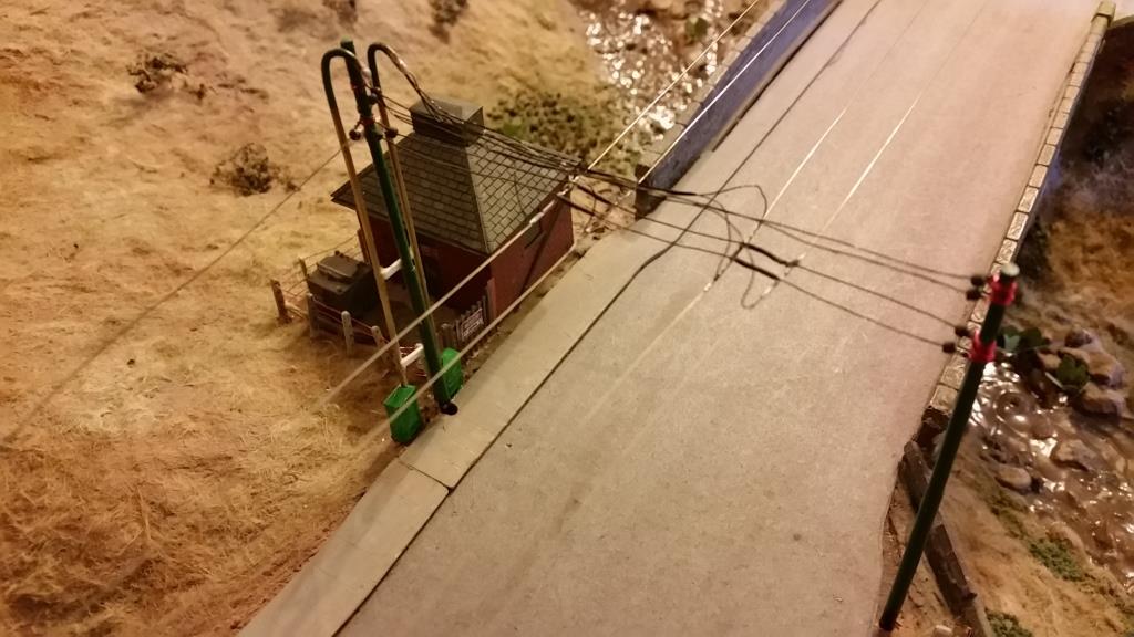
Here, the span wired have been double4d and the feeder cables strung. Quite a bit of painting still required. (>>)
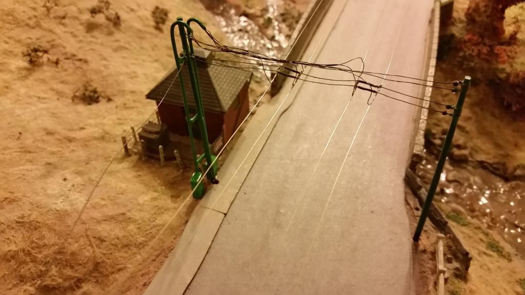
The finished article ready for use. (>>)
The feeders being approached by Bradford 704 on a test run.
This shot is with flash as it shows up the fine wires much better. Since this was finished, two others have been done.
(>>)
Above shows work on the overhead to allow trolleybuses to
return to town on the main road.
Here is the new feeder work being installed.
(>>)
Above is the first frog unit from Australia waiting to be spliced in instead of the previous not-very-good-at-working version underneath it. (>>)
Below is the new frog spliced into position. It is working well, although I've had to make sure the sizes of all the trolleyheads are the same. The unit still needs painting. (>>)
The junction fully finished.
(>>)
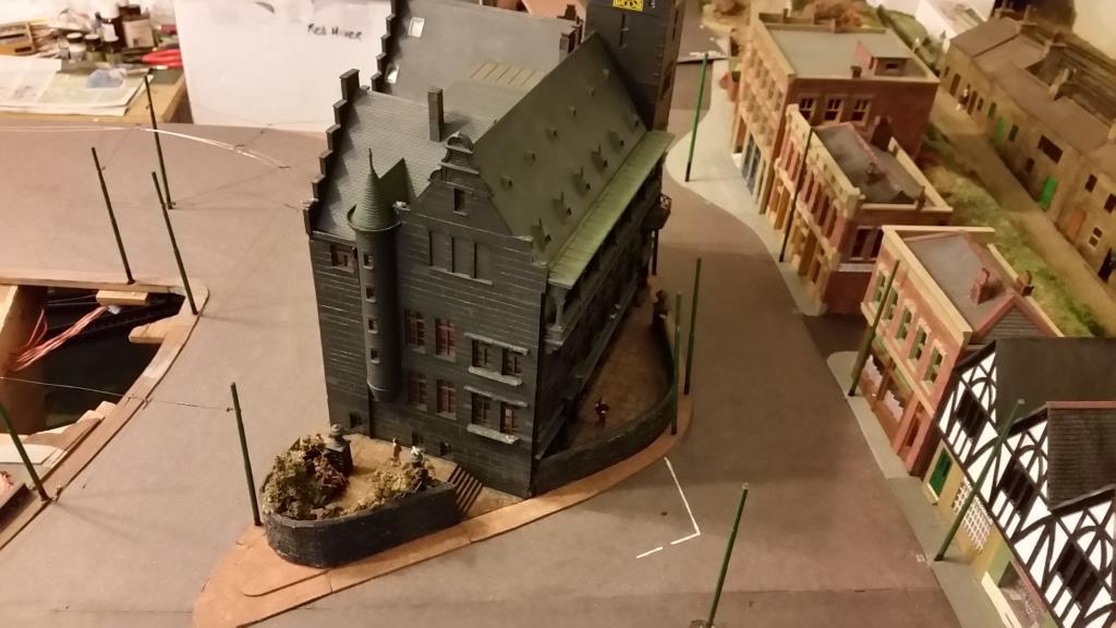
Meanwhile, pole planting has proceeded through the town
centre, to carry the overhead round the Town Hall. This has also entailed
getting the pavement around the Town Hall finished.
The next jobs are to string the various span wires and manufacture a couple
of overhead crossovers for in front of the Town hall.
Pics here and below.
(>>)
(>>)
(>>)
Various spans have been strung along the side and round the back of the Town Hall (>>)
First crossover under construction (>>)
The second crossing now attached, checking with template, from the wire side (>>)
The unit in position to check suitability; awaiting splicing in (>>)
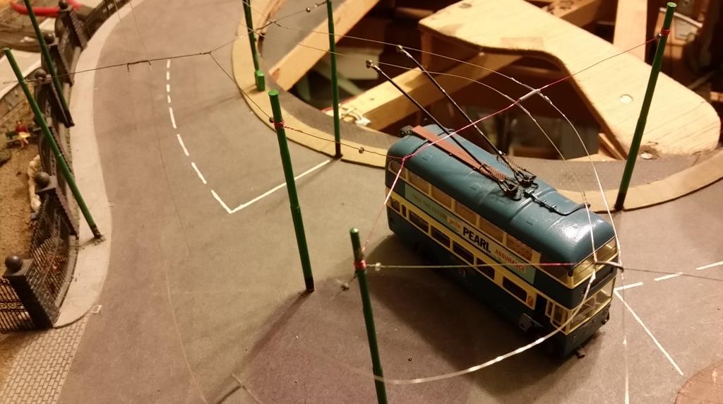
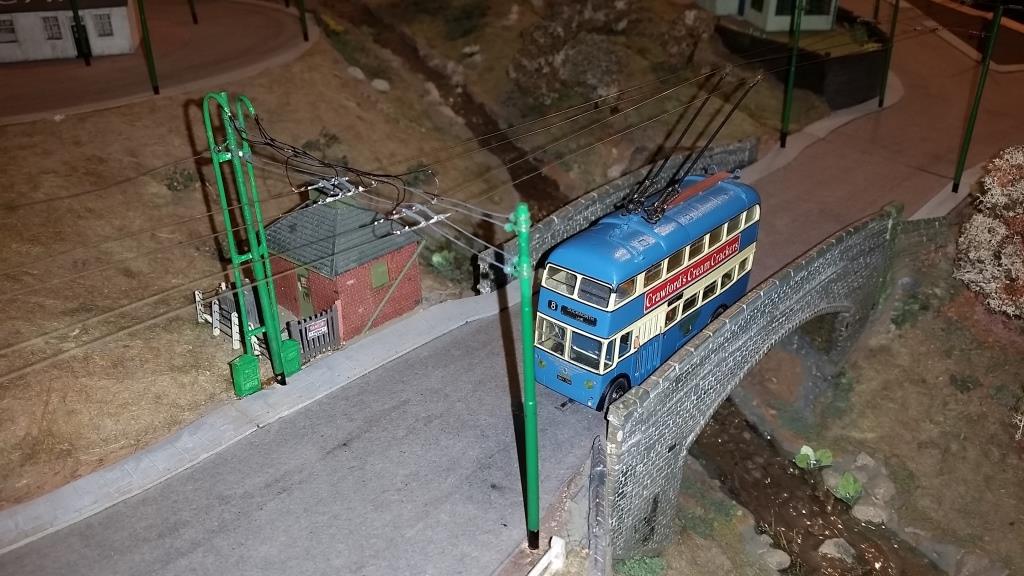
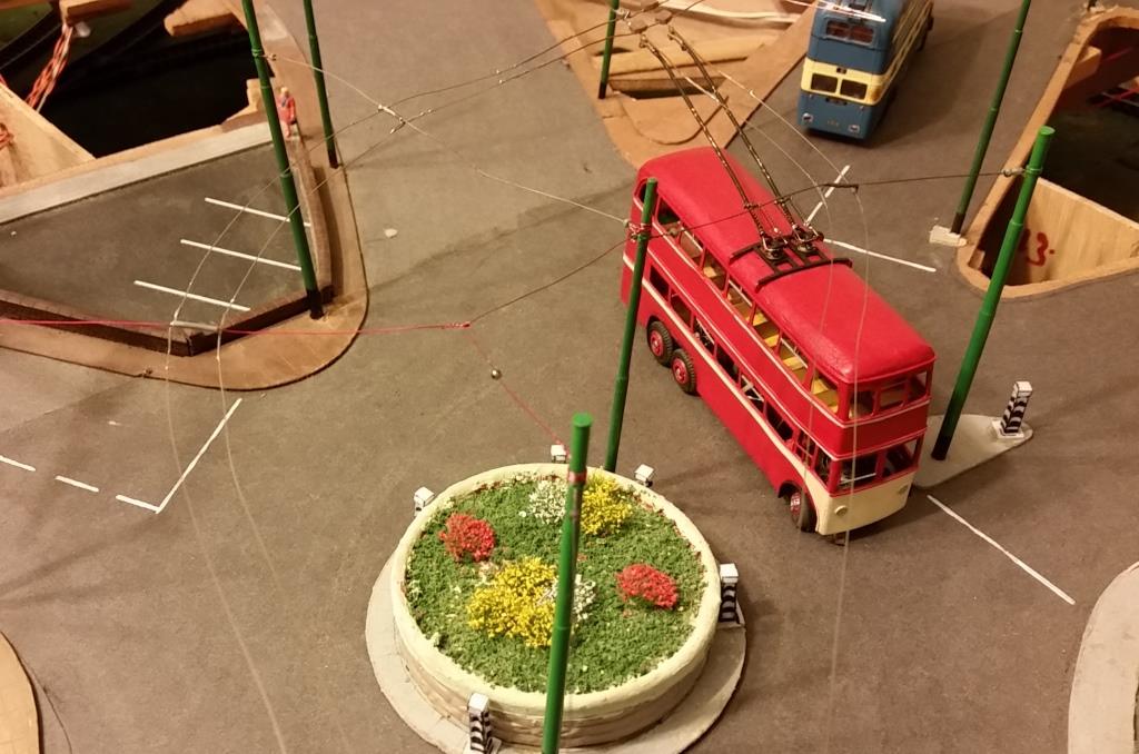
The first trolleybus to drive up the hill and round the roundabout in this direction. This new incoming wiring finished here at the time.
(>>)
The new crossovers being spliced into the existing wires. (>>)
The first trolleybus to use the new crossings after setting off from the Town Hall stop on the outgoing wires. (>>)
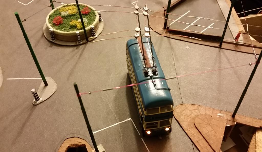
Bradford 704 does the honours again, the first trolley to cross over the outgoing wires on the new crossing. The wires now need to be extended around the back of the Town Hall from here. (>>)
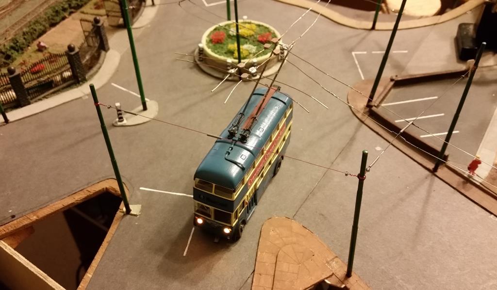
Another shot of the same location.
You can also see the second crossing which was built in for further expansion. (>>)
And we can now drive around the back of the Town Hall (which is not in position of course). 631 is about to try out the new but incomplete trailing frog into the existing wiring.
(>>)