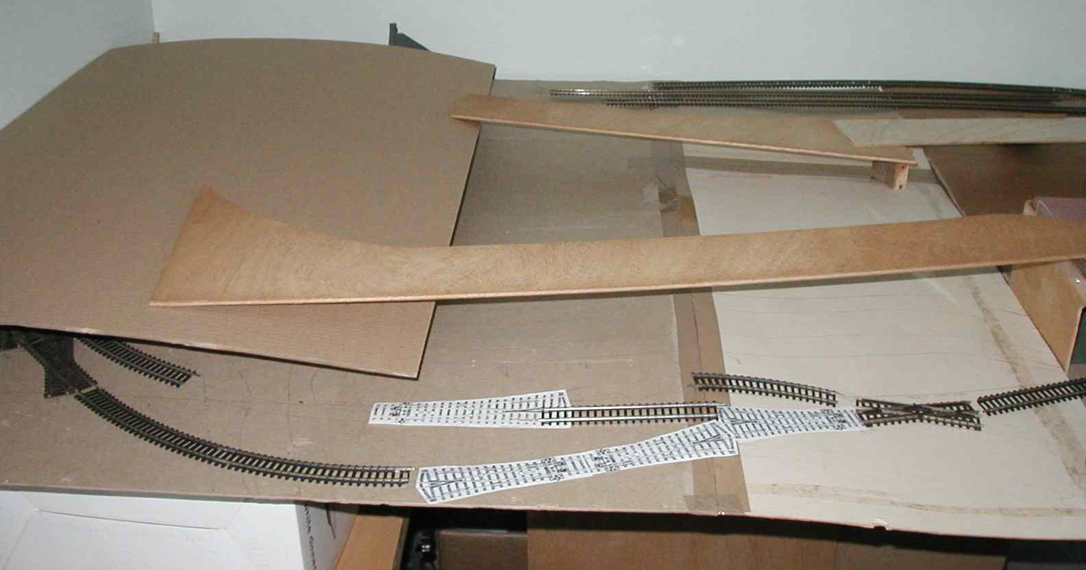
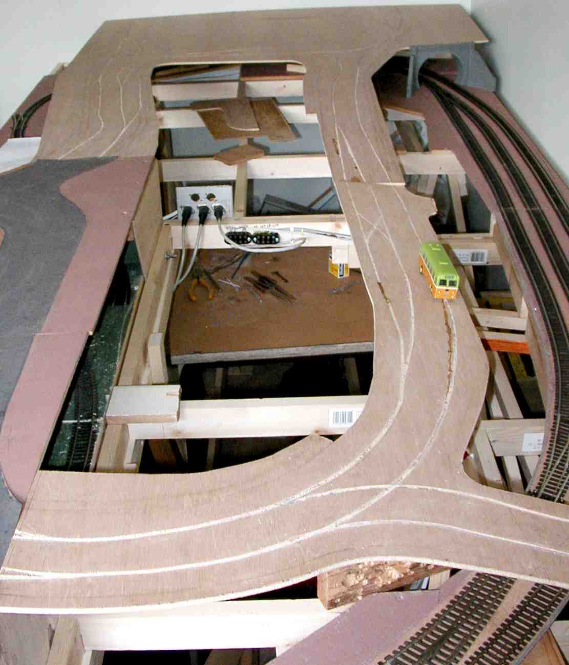
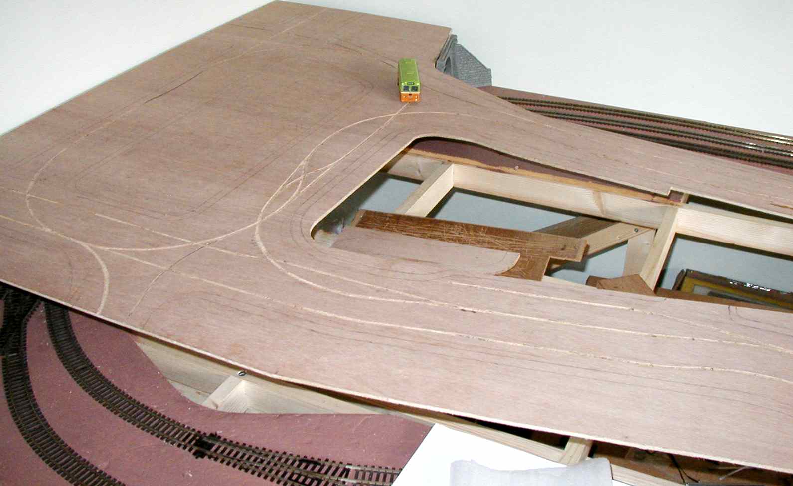
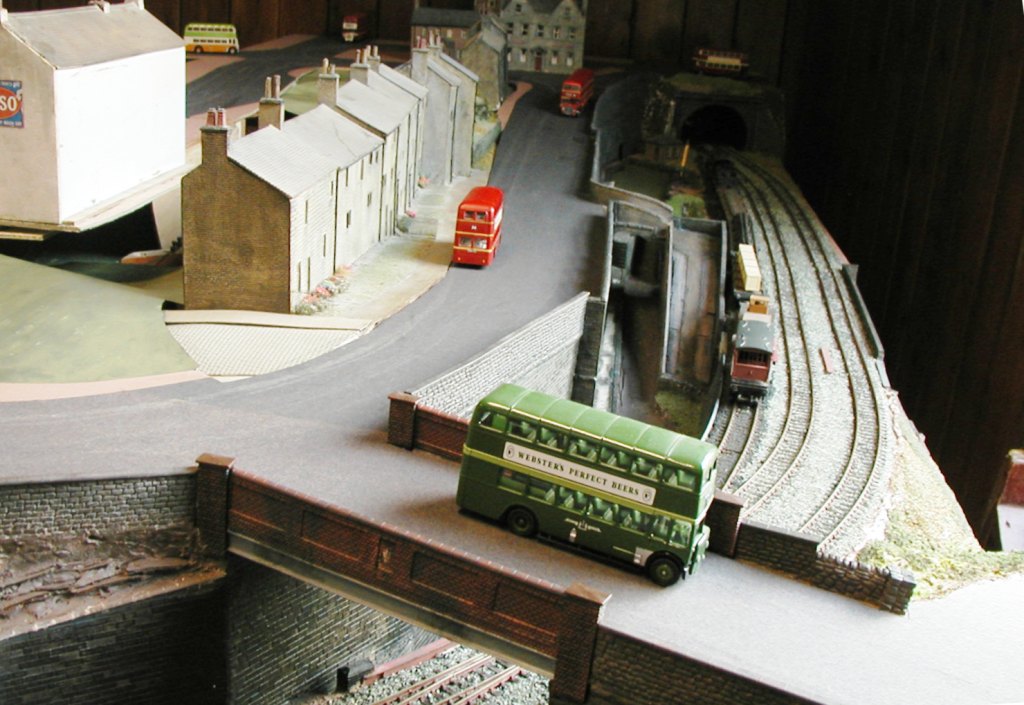
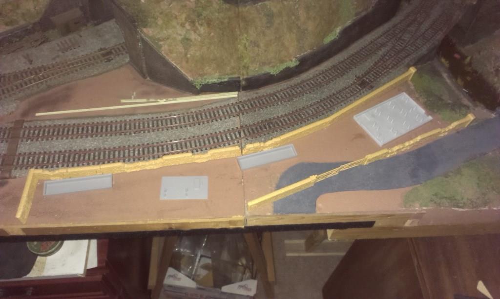
Board 6 with the road system. Obviously this has been mocked-up with straight bits of ply, and will eventually be sweeping curves. The large area on the left (covering a railway tunnel such that the trackwork seen here will not be on public view) will be a joint turning area for both roads, around some houses and shops. Further roads running off the edges will be tracked just in case I want to extend further, even though the room won't be big enough then! (>>)
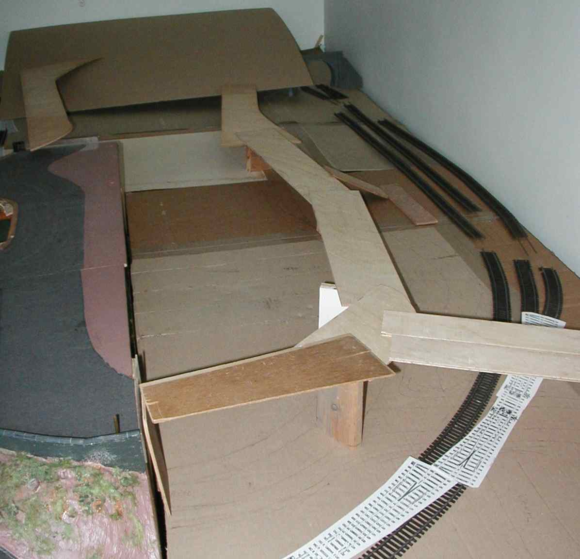
Back to Board 5 and the mock-up of the road system. There will be a canal in between the railway and the road in a dropped section to allow construction of a lock and some interesting bridges! (>>)
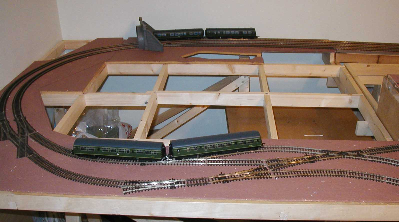
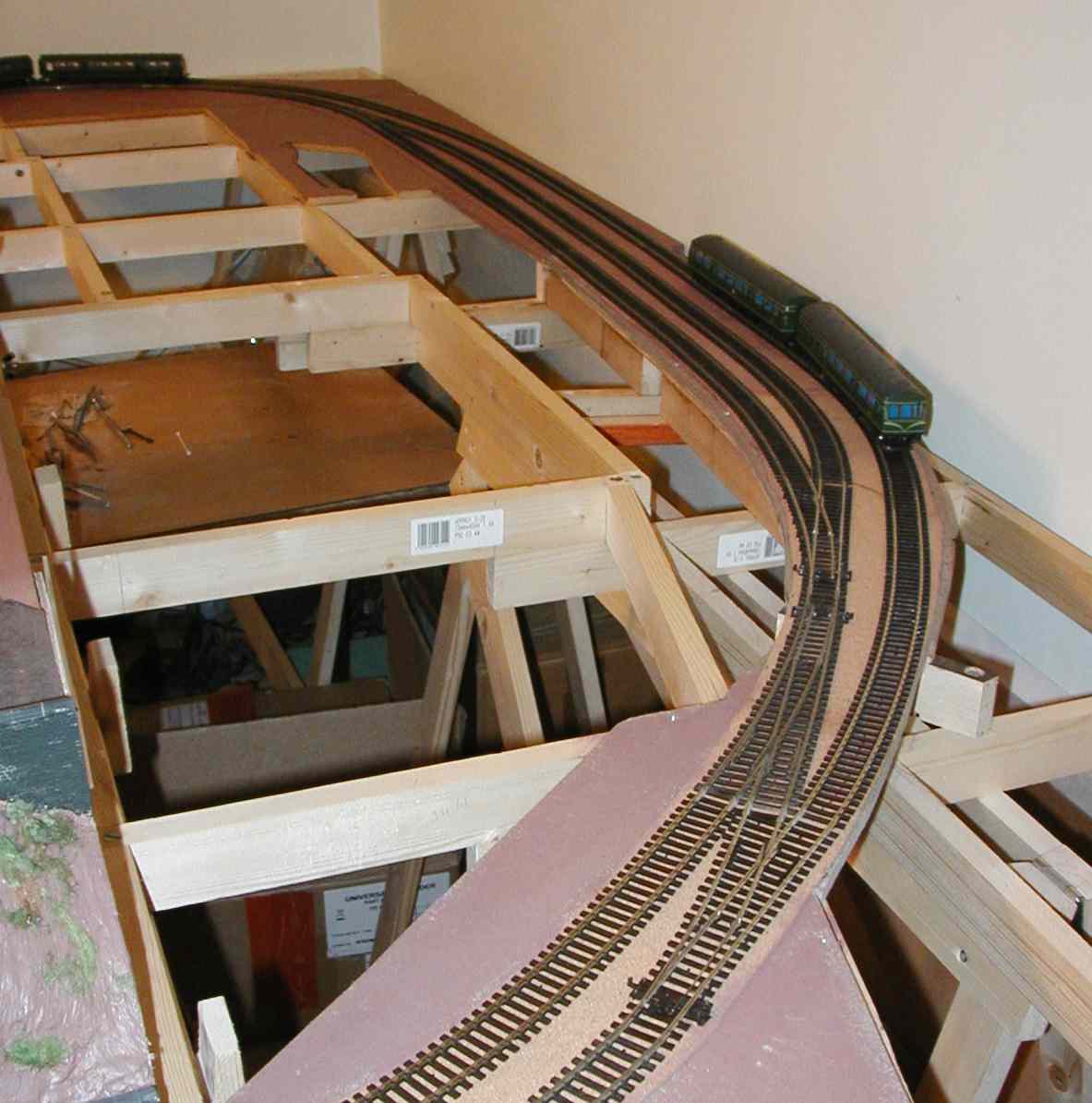
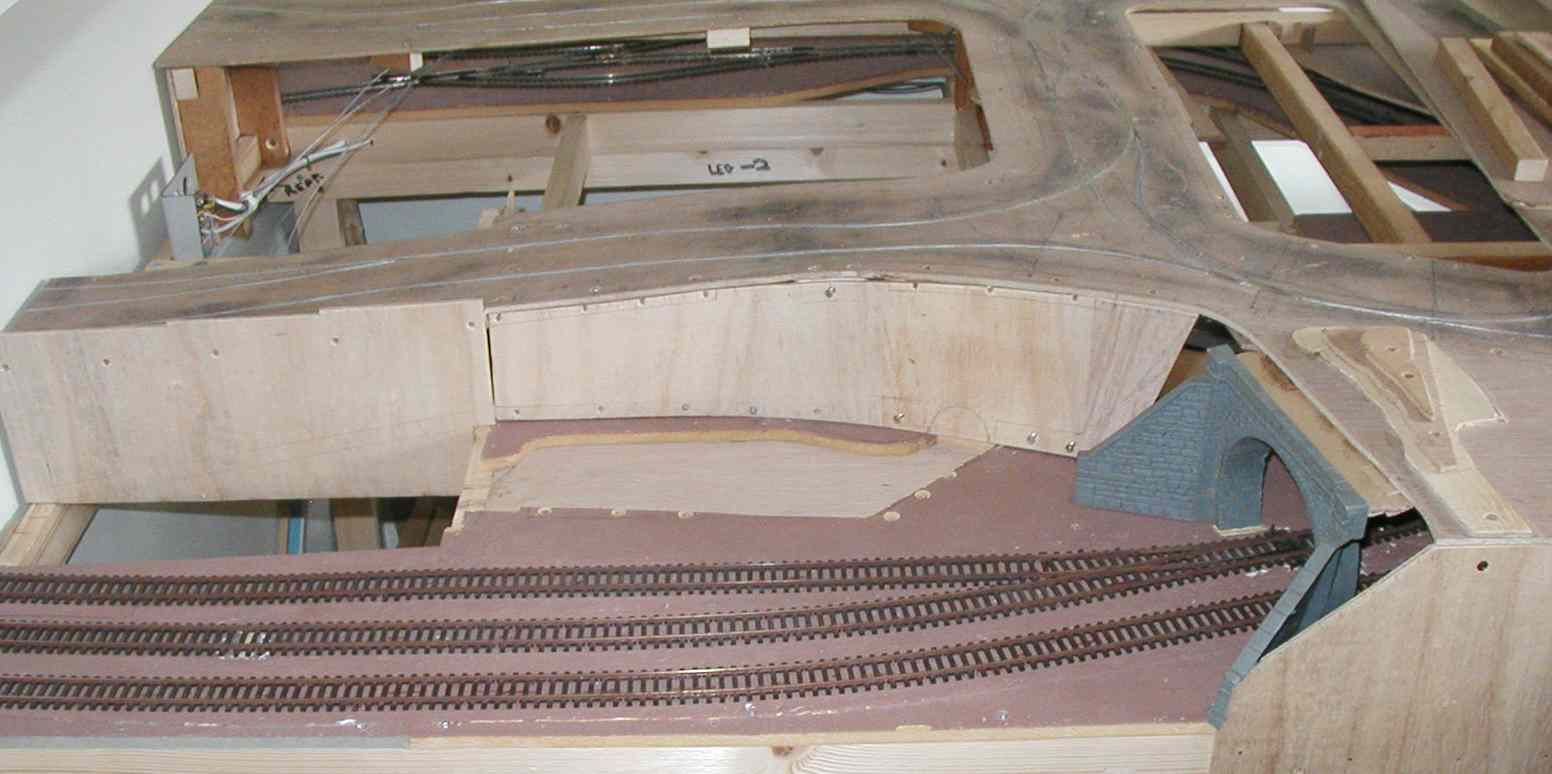
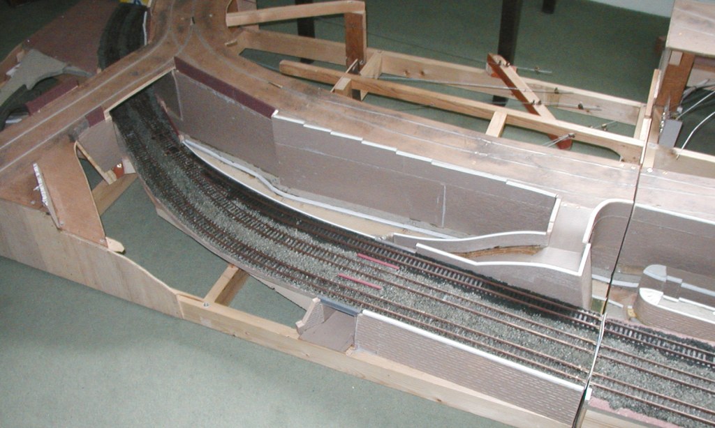
Two shots with the trackbed constructed, cork underlay down and
painted, point motor holes cut and the track laid properly after preliminary checking for
correct geometry. These shots also show a couple of class 101 diesel multiple units
testing the track (using flying leads).
Both main lines run back into Board 4 at each end. There will be a fiddle yard at the bottom left (not under construction yet).
(>>)
Still required at this stage was all the necessary wiring to make it fully operational, but the general concept can now be seen properly.
(>>)
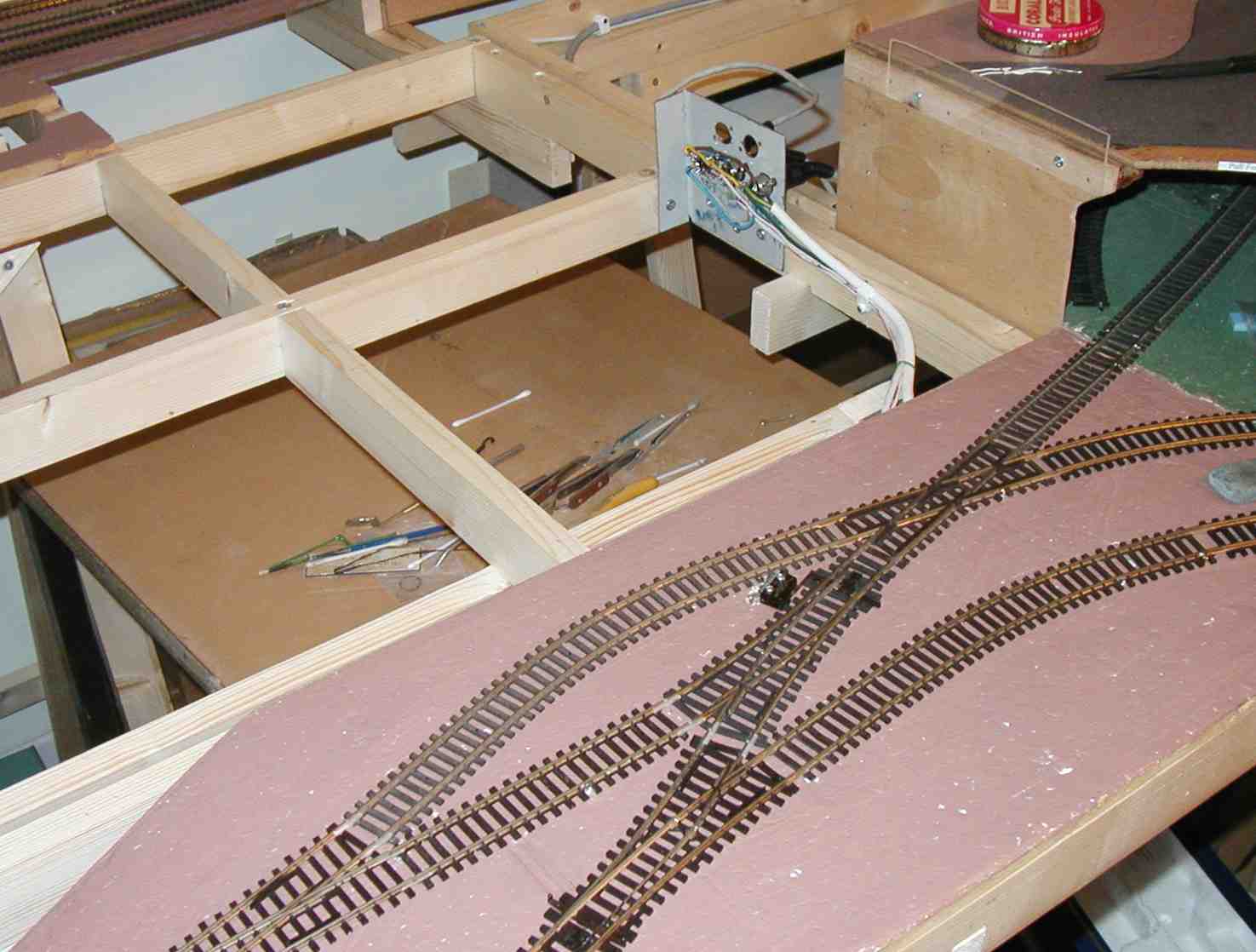
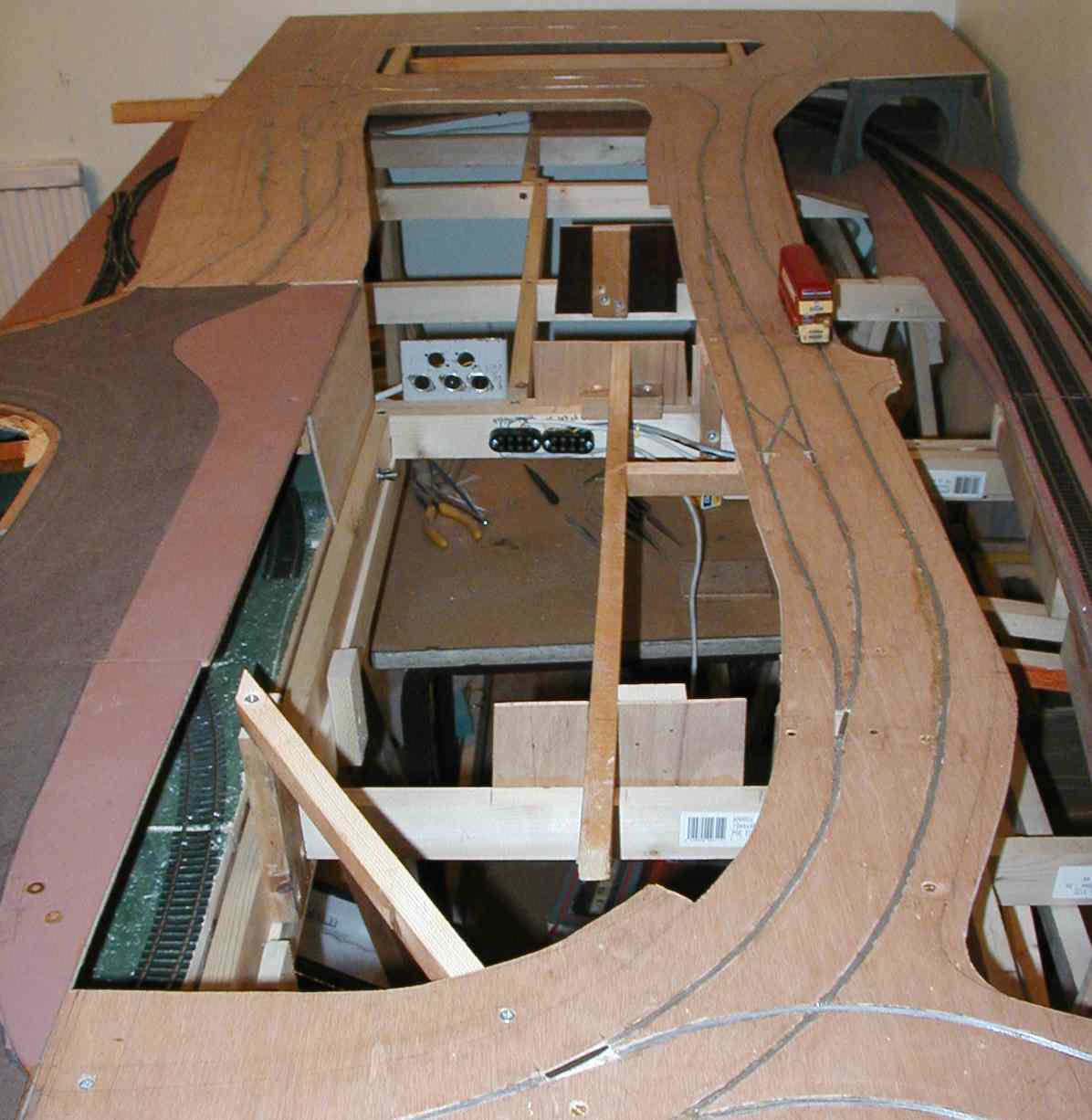
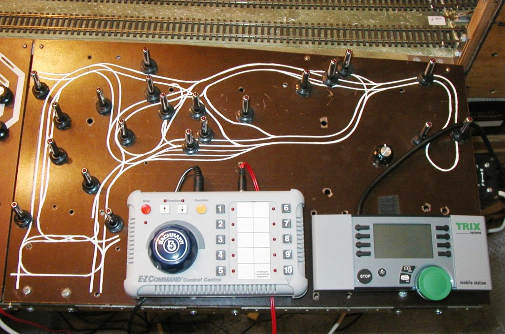
The wiring sockets between the boards and back to the control panel. Also shown is the essential microswitch on the point in the centre providing access to the reversing section. This is needed to switch the correct section into the reversing loop depending on the point setting. (>>)
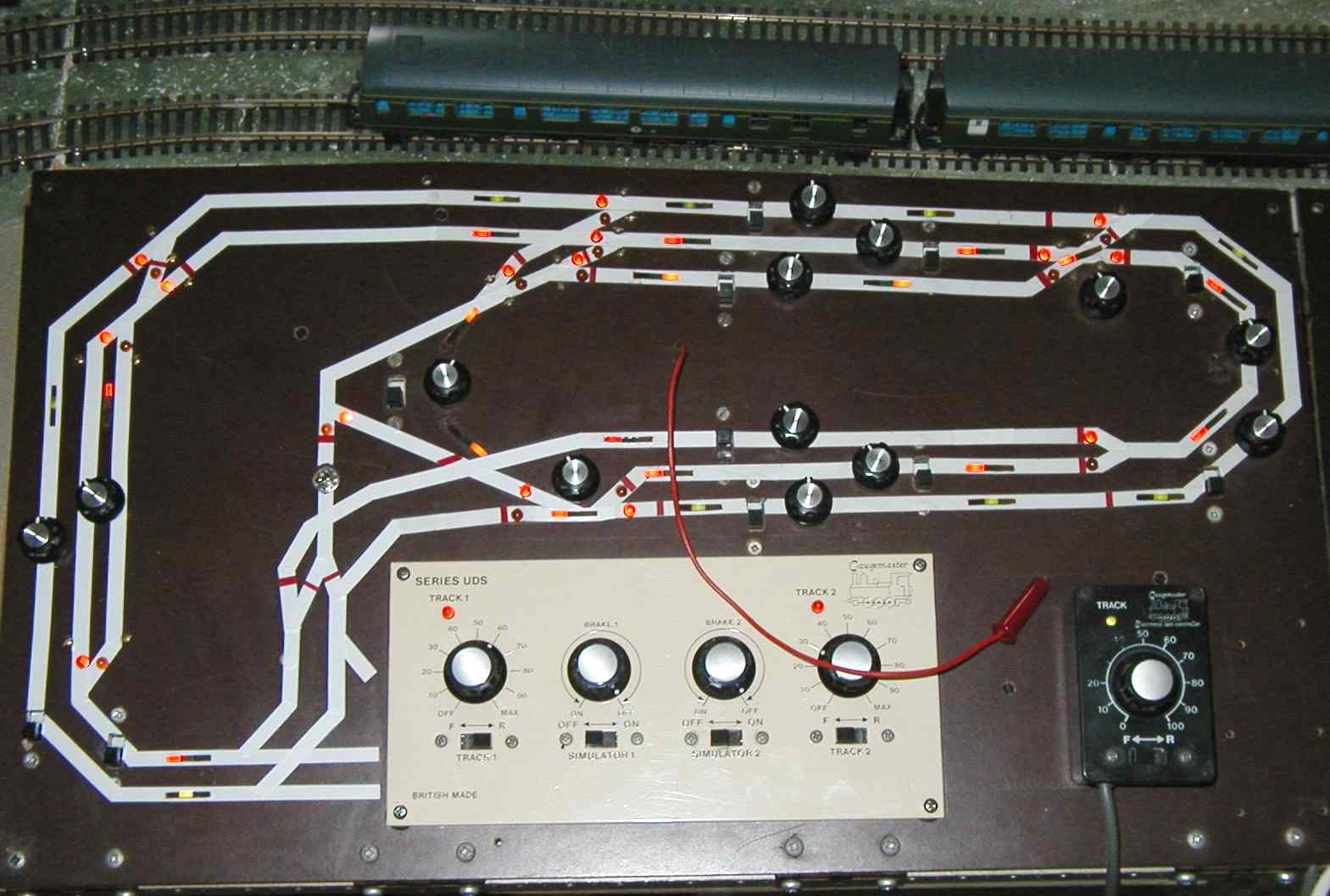
The control panel modified with the cab control lights and the point indicator lights on. The flying lead is for point switching. The reversing switch for the reversing section can be seen left-middle - the microswitch on the access point ensures that the reversing loop is powered from the correct main-line section. (>>)
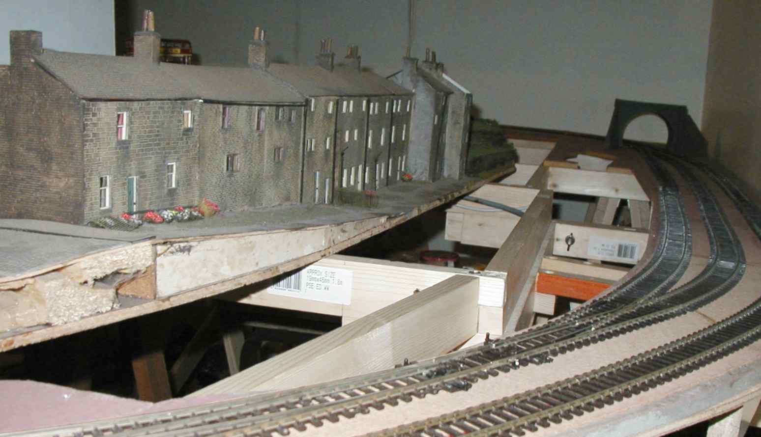
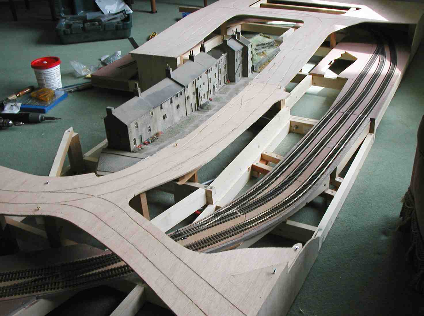
A row of terraces was already 'in stock' and this would be modified and then utilised along the new roadside which will be directly in front of these. The sweeping curve past these falls and then rises again as well, so the road had to match the contours of the row of houses. To the right of that you can see the dropped section which will become the canal, before reaching the railway embankment.
(>>)
 (>>)
(>>) (>>)
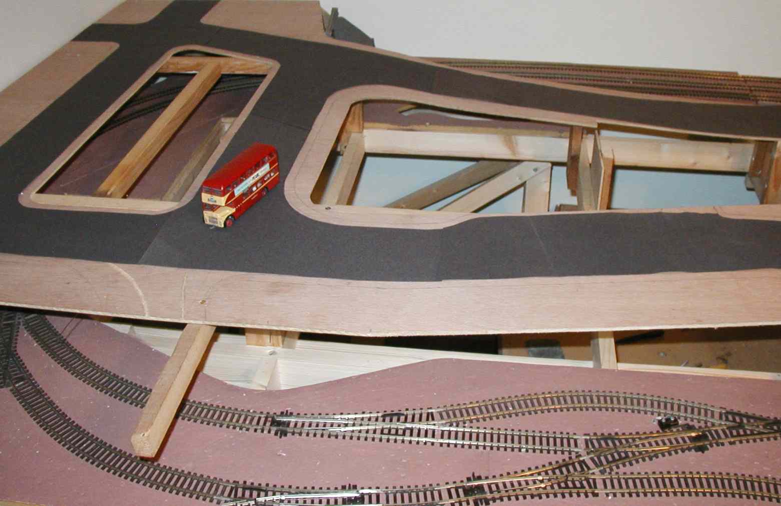
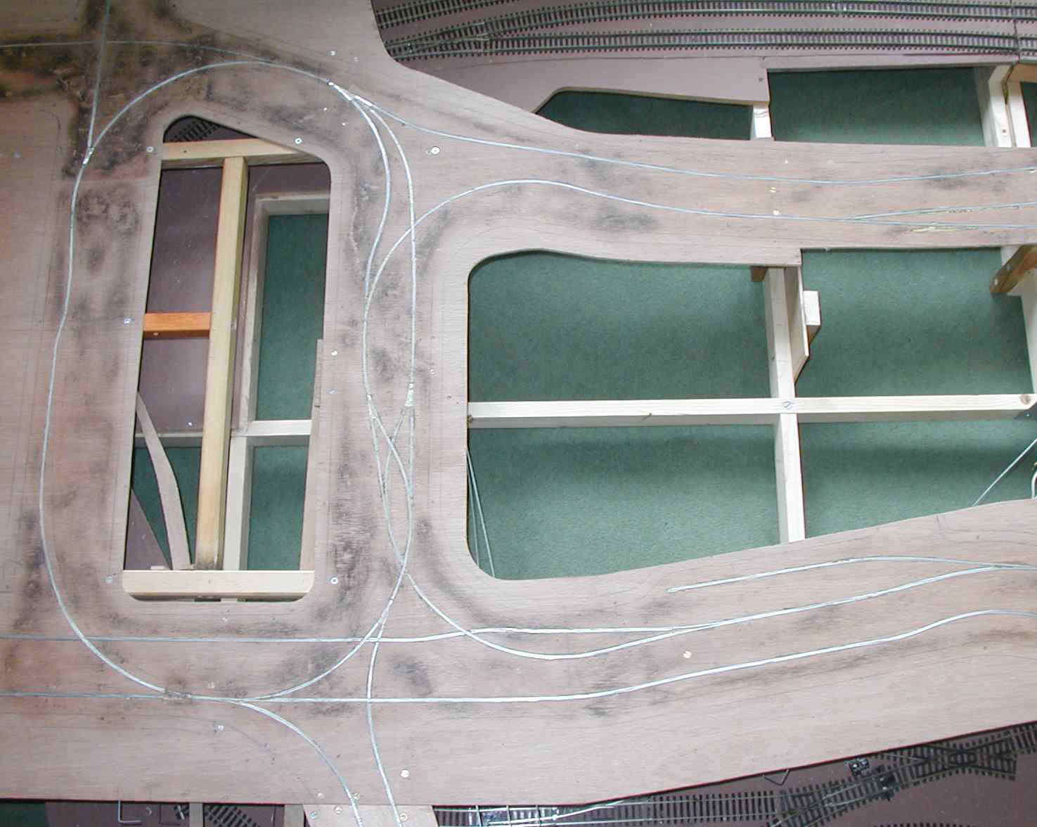
(>>)Two shots after the guide slots had been routed. I have provided several 'holding areas' for vehicles, so that they can be waiting in the wings, not blocking the main roads.
The road system has been made quite complex, as once everything's laid you can't change your mind and add bits!
However, I did decide to add an extra link after experience at the 2007 Sheffield Exhibition - see below. Some holding tracks run off the edges in case I want to extend again.
The extension boards assembled away from the main layout so I could work on all sides. Here the roadway supports have been constructed so that the slopes coincide with the existing housing module (now tided up), and the guideway grooves have been routed. The narrow channel for the canal is more apparent now. (>>)
Guide wires inserted, and the essential points made operational. (>>)
Temporary roadway laid to enable testing with one of the Huddersfield motorbuses. All successful so far!
The extension was therefore ready for operation at
the the Sheffield Exhibition on the 23rd June 2007 - see photos on the main Ridings page.
(>>)
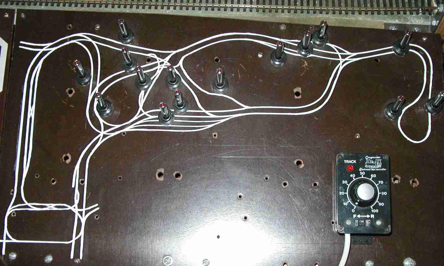
The control panel updated with the road mimic diagram. As the bus stops had not been fitted at this stage, there are no switches yet for these.
The space at the bottom was for further controllers, but these have been superseded by adopting DCC control - see 'Latest' Page for information on the DCC additions.
(>>)
These included: improving the board connections to make them more level, adding the short 'fiddle board' to the bottom of the picture on the right, inserting the remaining guide wires to the board edges, finishing the points and control wires, and laying a new link past the bus stop on the main board. It was discovered that this was required as vehicles returning by the short route to town could not get past a parked vehicle at the right-hand bus stop (see right).
The rail joints have now been strengthened, so the next jobs are to start on the structure of the scenery, paint and ballast the track, and sort out the tunnel entrance.
The track modification mentioned on the left can be seen here, linking the upper road to the passing loop down the centre. Yes, its all pretty complex! (>>)

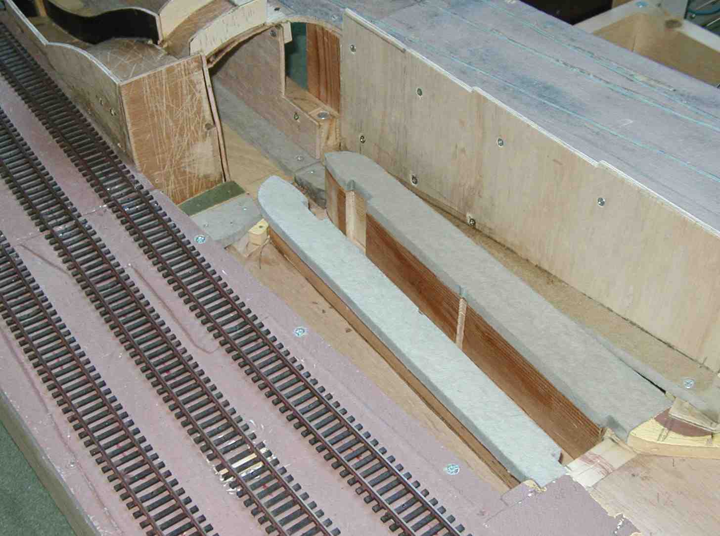
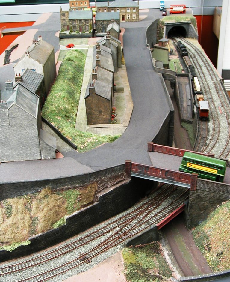
This picture shows the other, smaller, board with its point control wires. The scissors crossover is to enable the parking of vehicles in the siding with other vehicles arriving or setting off past them. The road bridge design was the next to be worked out - it was complicated by the canal. This occupies the 'slot' between the railway and the road, then snakes under the railway. In the picture on the right the canal floor and banks have been laid, and a retaining wall and a bridge have been constructed. Obviously all this still needs cladding with walling etc. (>>)

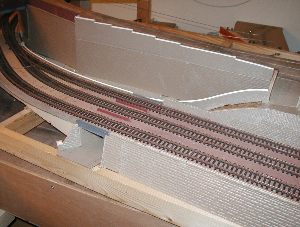
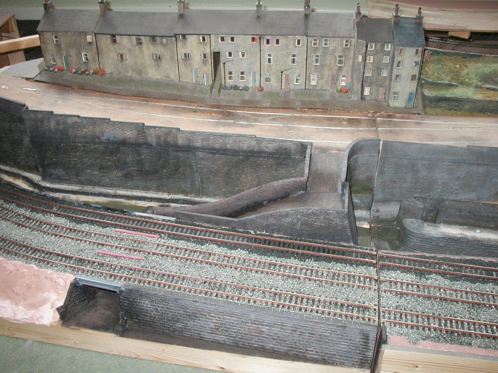
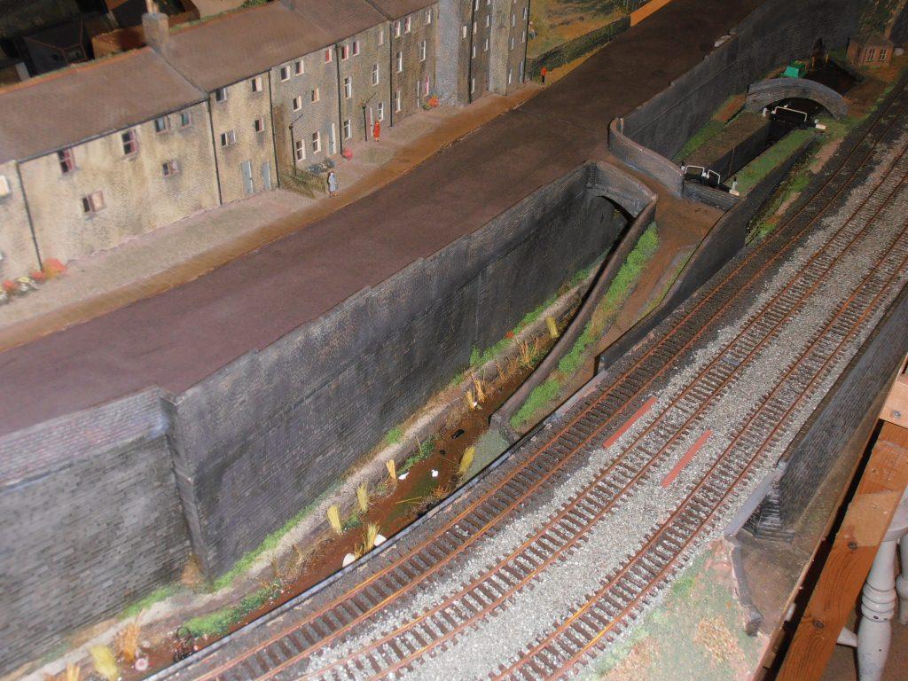
Here with the track weathered, all the retaining walls in place, and the two railway bridges created.
The area at the front will become grass banking.
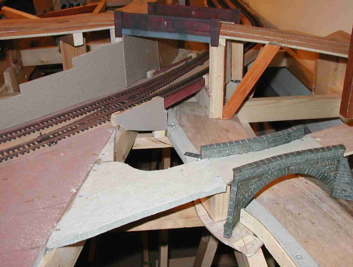
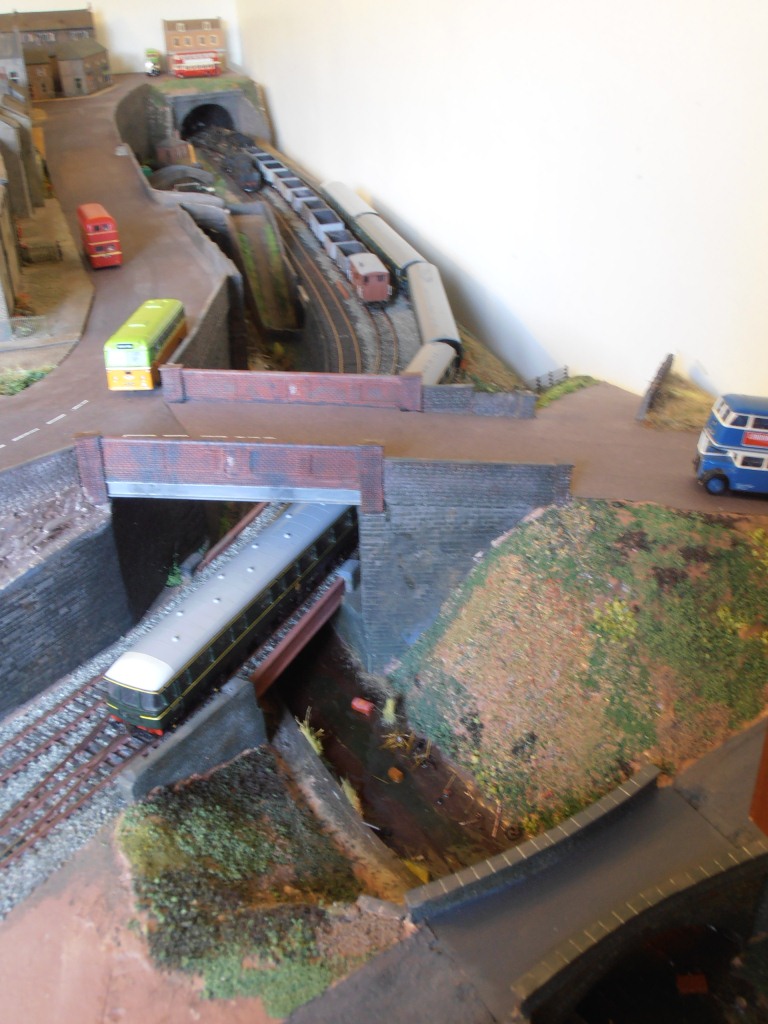
The road bridge has been started but still requires side-walls. It can now be seen that the road crosses the railway and the canal at the same time - a triple-layer bridge!
(>>)
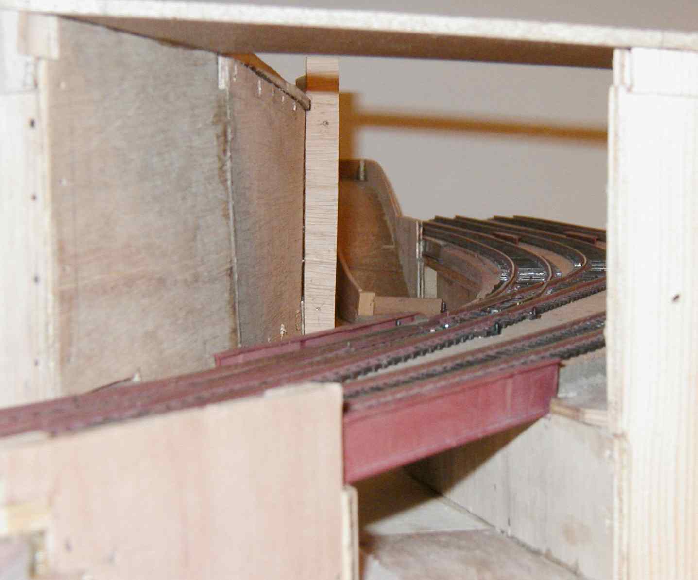
A view through the three-tier bridge. (>>)
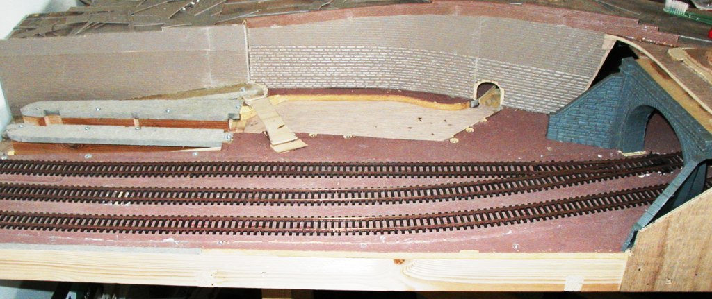
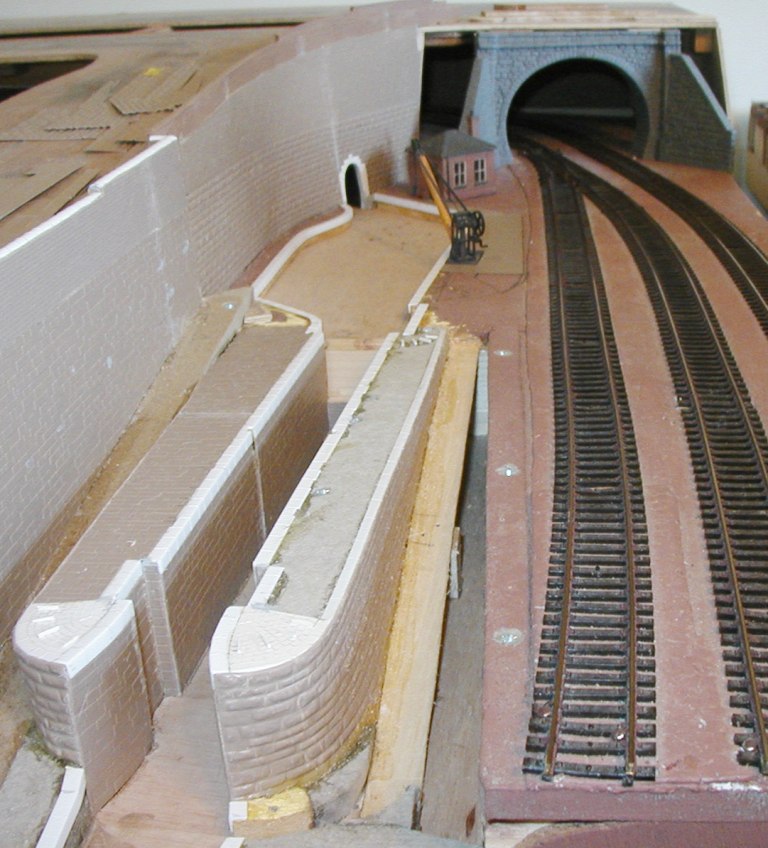
Turning to the other end, the railway tunnel entrance saw some work, as did the retaining walls, and the canal basin floor. The canal lock will be in the dropped section to the left. The canal finishes at Tunnel End! The canal will disappear into a tunnel here, just as the Huddersfield Narrow Canal does at Marsden. (>>)
The canal lock starts to make an appearance -the basic lock walls have been surfaced.
The bridge connecting the main road with the track that dives under the railway has also been constructed.
There are a lot of walls to clad to finish this section!
(>>)
The roadway at the top gets its bridge sides. This is a Wills kit which has been modified to suit the slope and extra length of this bridge. A canal bridge is required for a minor road here, so another Wills kit has been used. Most canal bridges in the locality were tapered towards the middle and it has been 'skewed' to suit the diagonal nature of the crossing. (>>)
.A view from the other side of the bridges with the stonework being applied. (>>)
Attention turns to the other Extension board, and the canal walling gets cladded, with the tunnel entrance being picked out for the first time. The canal bridge still needs to be arched into place - I'm waiting until it won't be in the way. (>>)
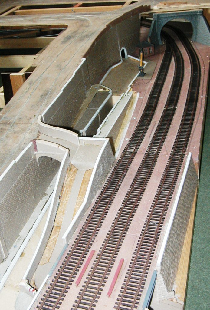
An unusual view from the end showing the lock preparations and the two tunnel mouths. The bridge and lock gates still need installing. (>>)
A long view with the walling finished but not painted. (>>)
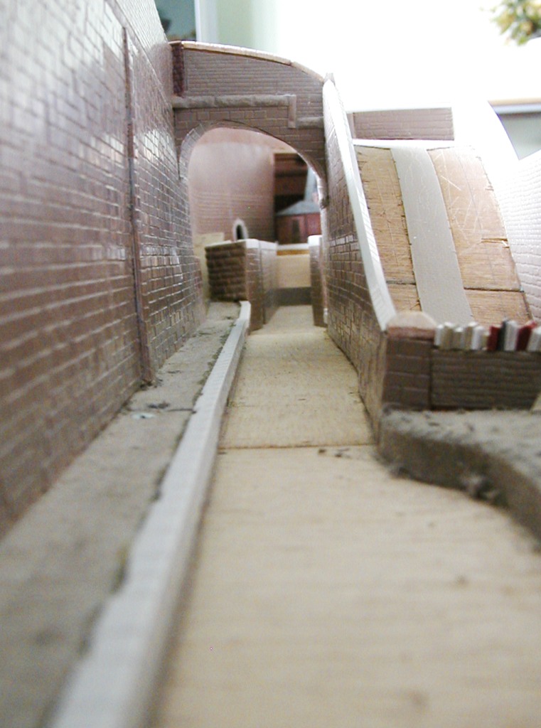
An atmospheric shot along the canal, looking into the lock throat. The canal tunnel can be made out in the distance. (>>)
The railway track is now ballasted - a very tedious job, but you have to do it eventually! The loop has been 'ash ballasted' while the main lines are regular granite.
This board now requires it's hillsides at the front - mainly on the left hand side, to blend in the roadways and the trackbed.
The extension boards needed their bus stop solenoids fitting - these were put on order while the switches for them were fitted and wired up. This shot also shows the Trix DCC controller. After the solenoids arrived they were fitted and wired back to the control panel. (>>)
All the walls weathered and a start has been made on making the canal look abandoned. Compare with the picture above. The roadway still needs its covering of 'asphalt', which could not be applied until after the solenoids had been fitted and tested. (>>)
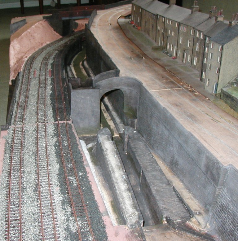
A shot from above the tunnel mouth along the railway and canal. (>>)
The extension in use at the Sandtoft Model Weekend 2008. Compare with the previous picture. (>>)
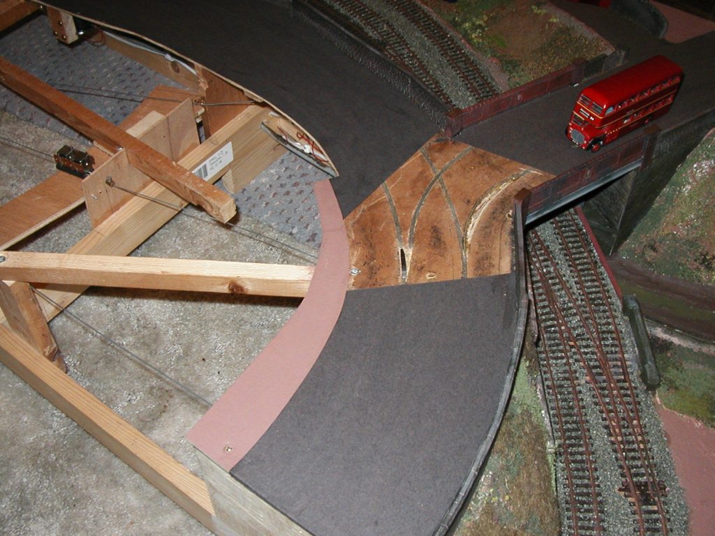
Photo of the arrangements taking shape on Board 5. The first point motor is on the left and the point can be seen in the foreground. I had to 'dig the road up' as the point itself had broken, and I also needed to alter the rightmost curve as buses hit the wall coming round it. (>>)
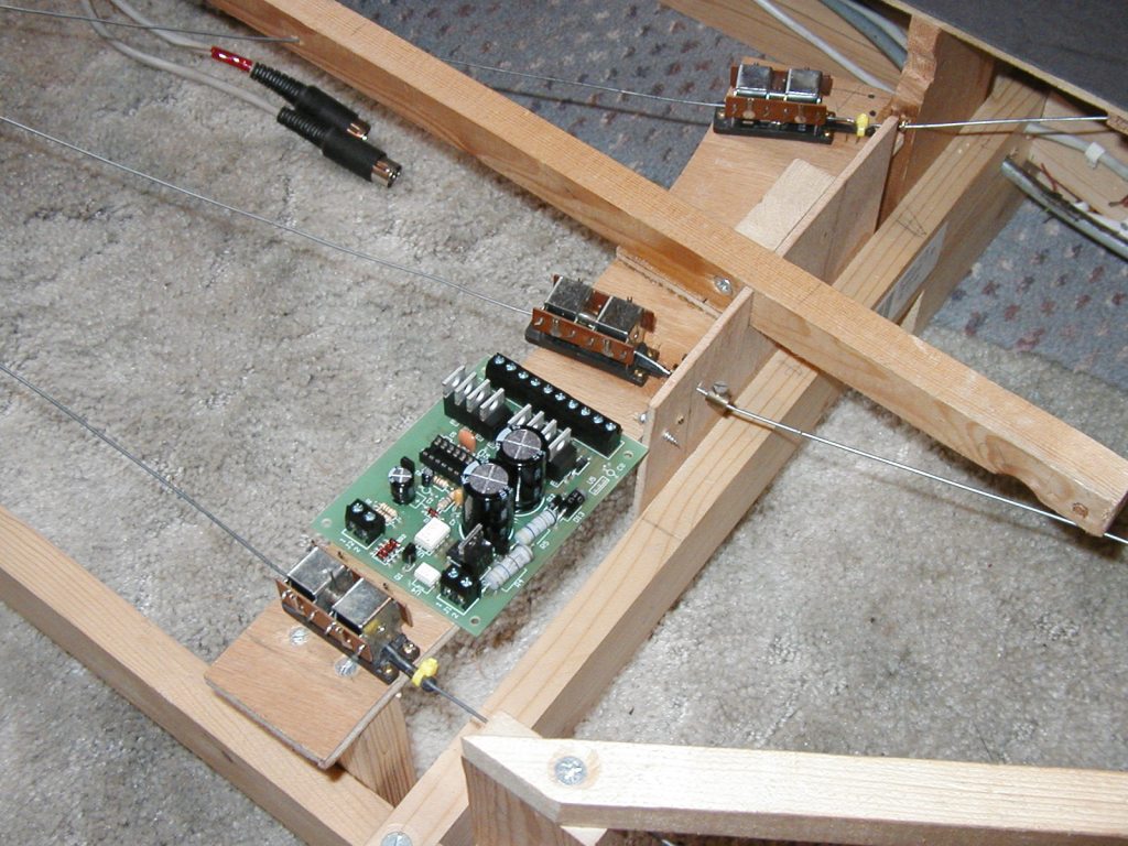
All 4 point motors fitted to Board 5 now. Here are 3 of them, along with the built MERG DCC Decoder (not in its final resting place). Board 6 had yet to be dealt with. (>>)
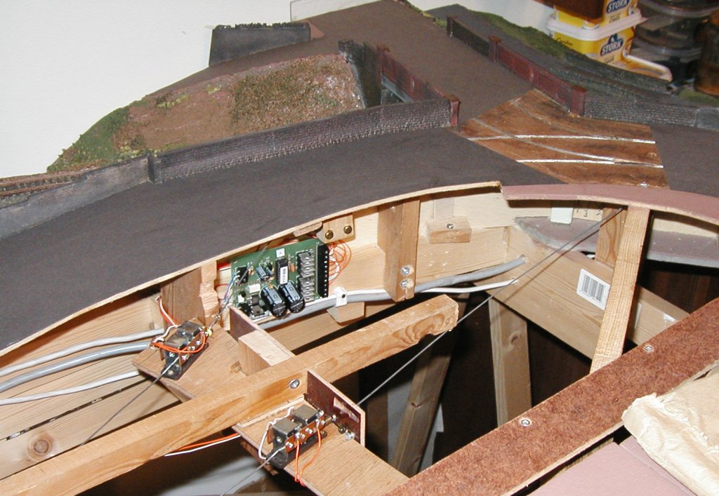
The Decoder board fitted under the roadway supplying the four point motors on this part of the layout. (>>)
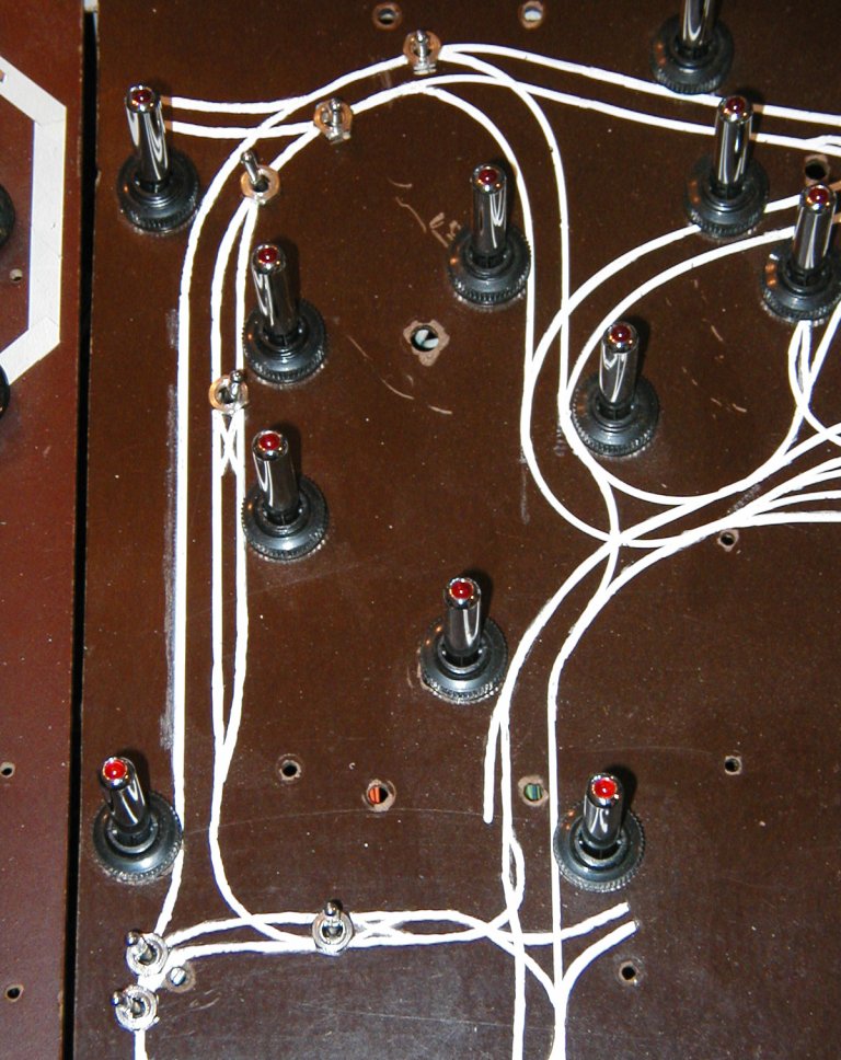
To the right is a shot of the seven point switches in place (4 for Board 5, 3 for Board 6). The MERG Encoder is of course inside this panel. (>>)
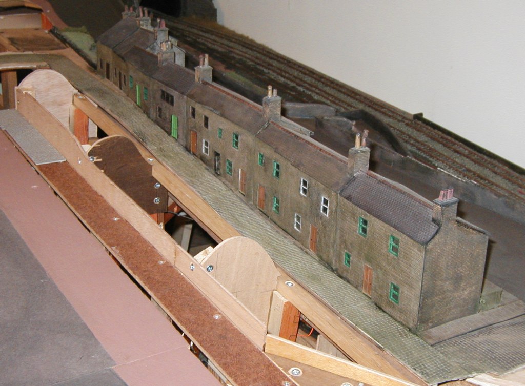
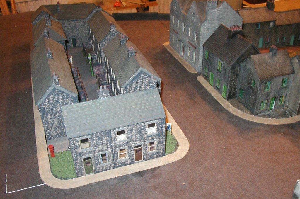
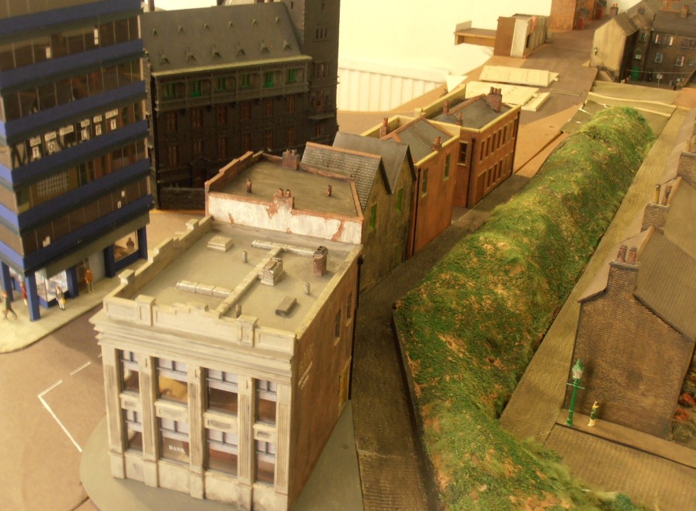
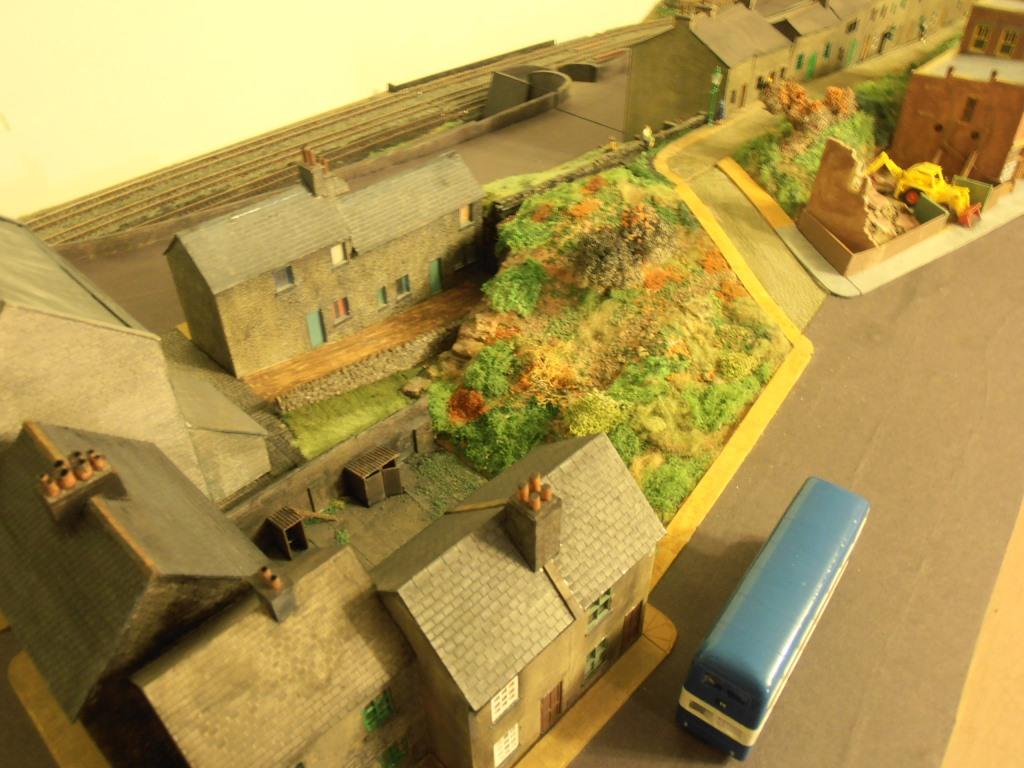
Meanwhile, the backs of the long row of houses was being detailed, having previously been plain plasticard. The formers are also installed ready for the scenery here, which will be a banking forming a natural break between the town and the canal area. (>>)
This is a shot taken at the Bradford Exhibition in April 2009, showing the grassy bank now in situ behind the row of houses.
More pictures from the Exhibition can be found on the main page. (>>)

Due to my having far too much to do, I have commissioned a housing module to be built by another modeller. This is the central section at the Extension's terminus (above), so it was particularly convenient to provide him with the base-board that fits the hole. Meanwhile I worked on the houses in front of this, the short row of elderly terraces in the right-hand corner was the first to be finished.
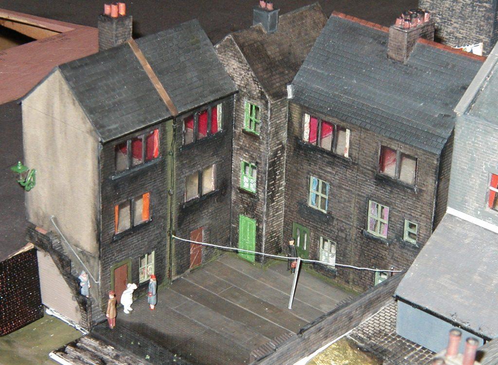
The 3-storey corner group after detailing the back yard and adding steps and a gas lamp on the wall. (>>)
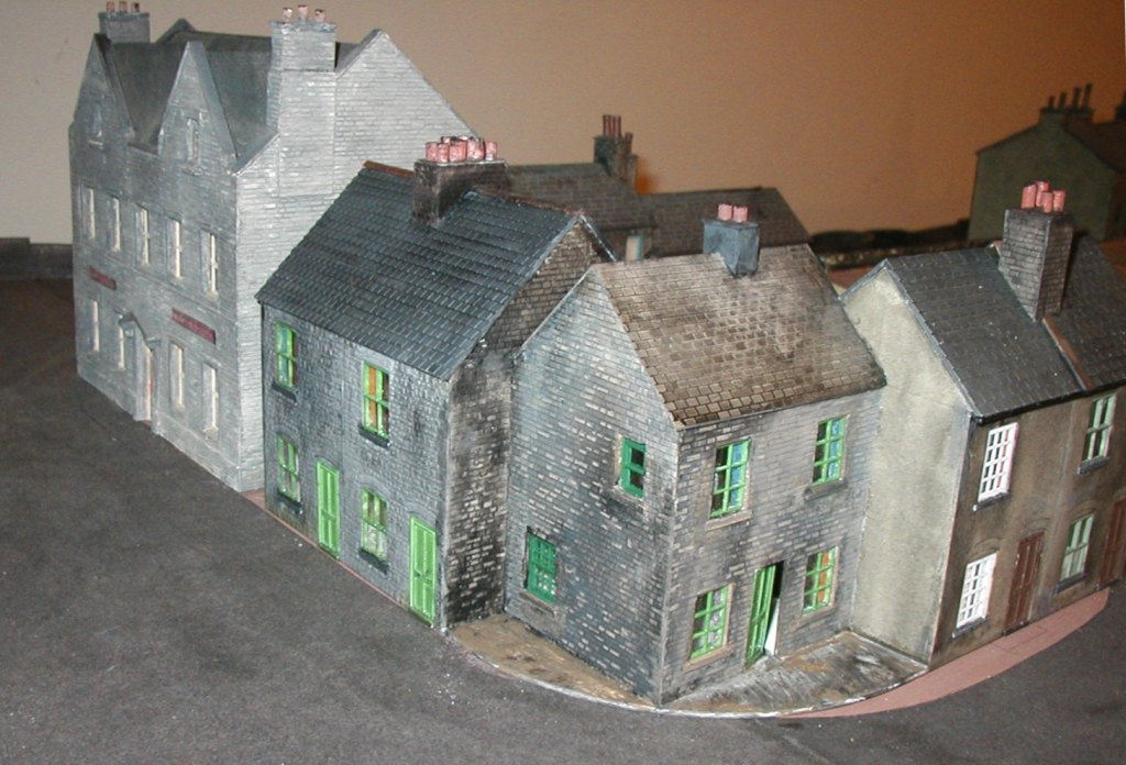
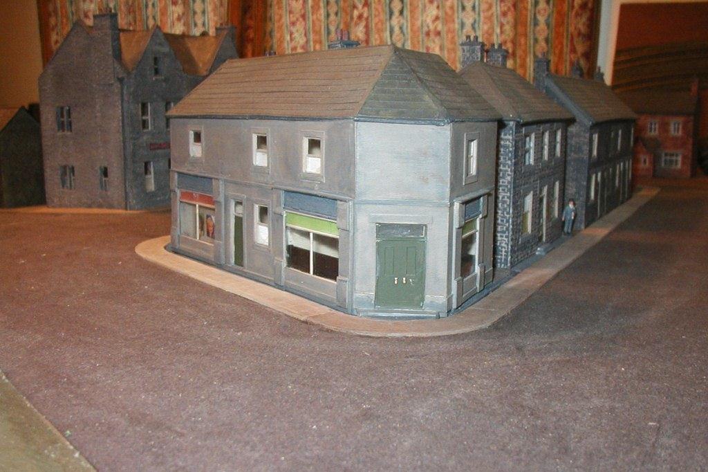
The same block from the front, with the pub "The White Lion" at the side. (>>)
The next job will be fitting pavements.
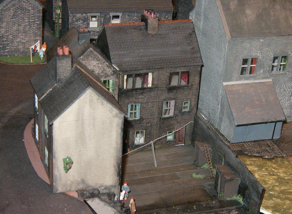
A different back view showing that the housing module behind has also been detailed - gas lamps and a washing line can be seen. (>>)
Pavement work has been going on, as shown in the two shots here of the central block of houses and shops (above and right). (>>)
Whilst I don't like doing the pavements, they do help to finish off the street scenes. Compare with photo above. (>>)
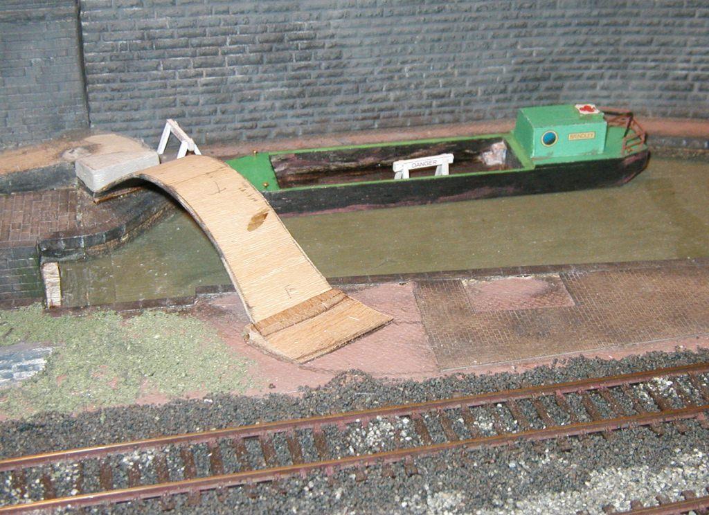
Meanwhile, the canal is receiving attention. A maintenance barge has been built, the bridge is ready to be added when the water has been poured in, and the lock gates are under construction. (>>)
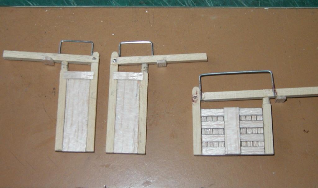
The canal lock gates constructed from a Craftline kit (as was the barge). (>>)
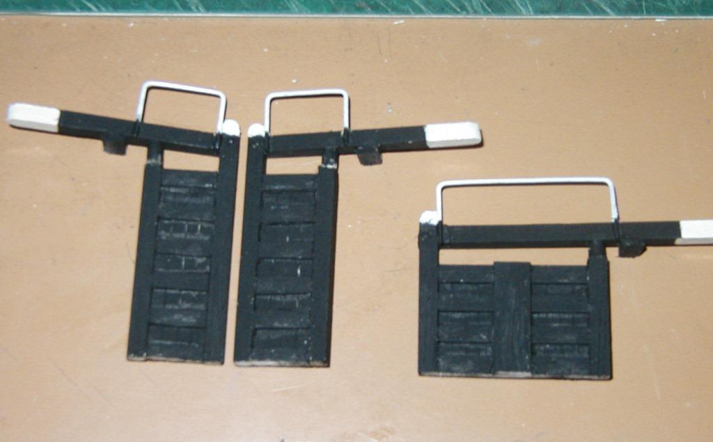
The gates are painted and ready for installation. (>>)
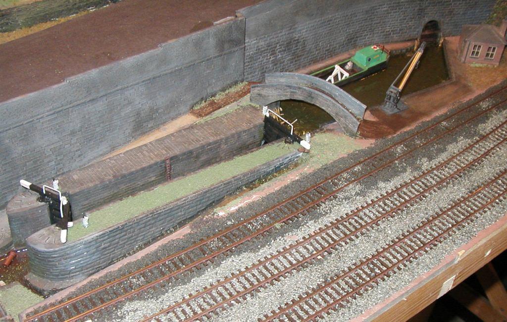
The gates installed and the bridge finished. (>>)
Water and 'junk' have been added to the lock to complete the picture. (>>)
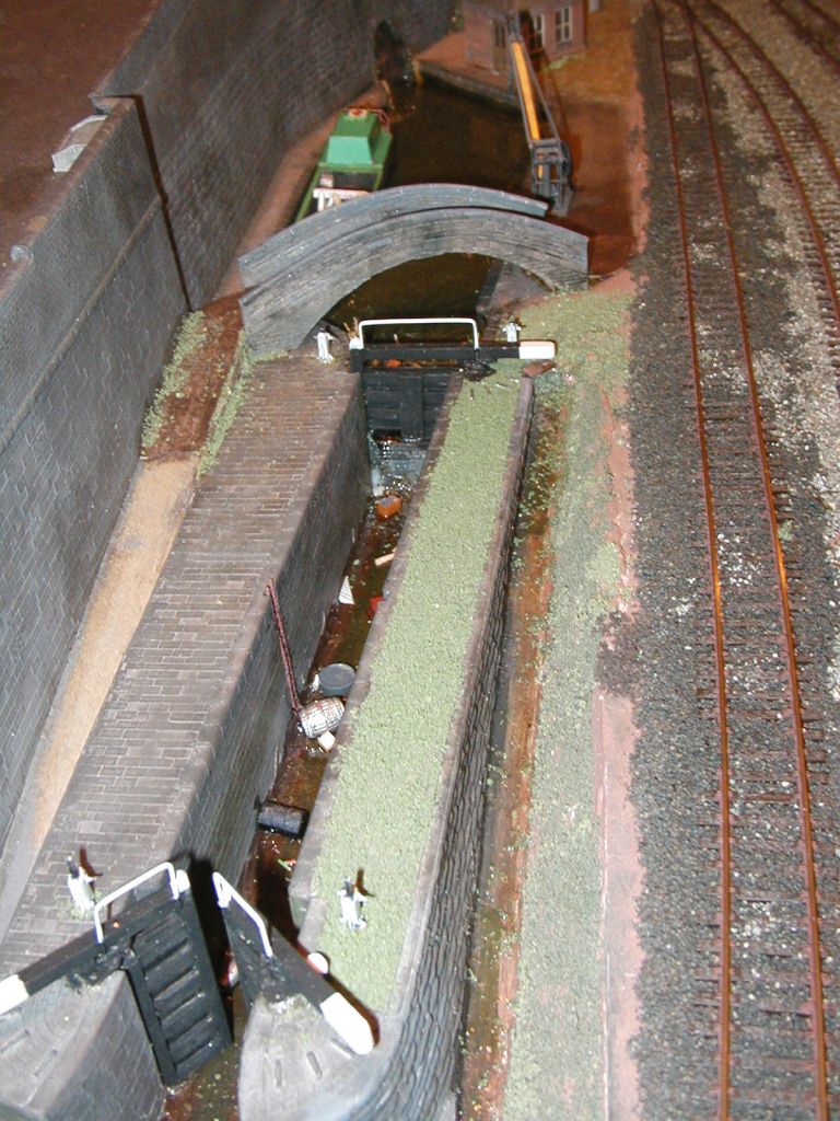
The rest of the canal needed to be treated the same way as
the lock. The theory is that the local Canal Society have made a start on
restoring the canal, but so far have only managed to clear the weeds from
the very top section, refurbished a maintenance barge and painted the lock
gates. Many years of clearing junk, weeds and accumulated silt would be
required before the canal would be navigable again. Thus the lower stretch
of the canal is still filled with foliage and debris.
(>>)
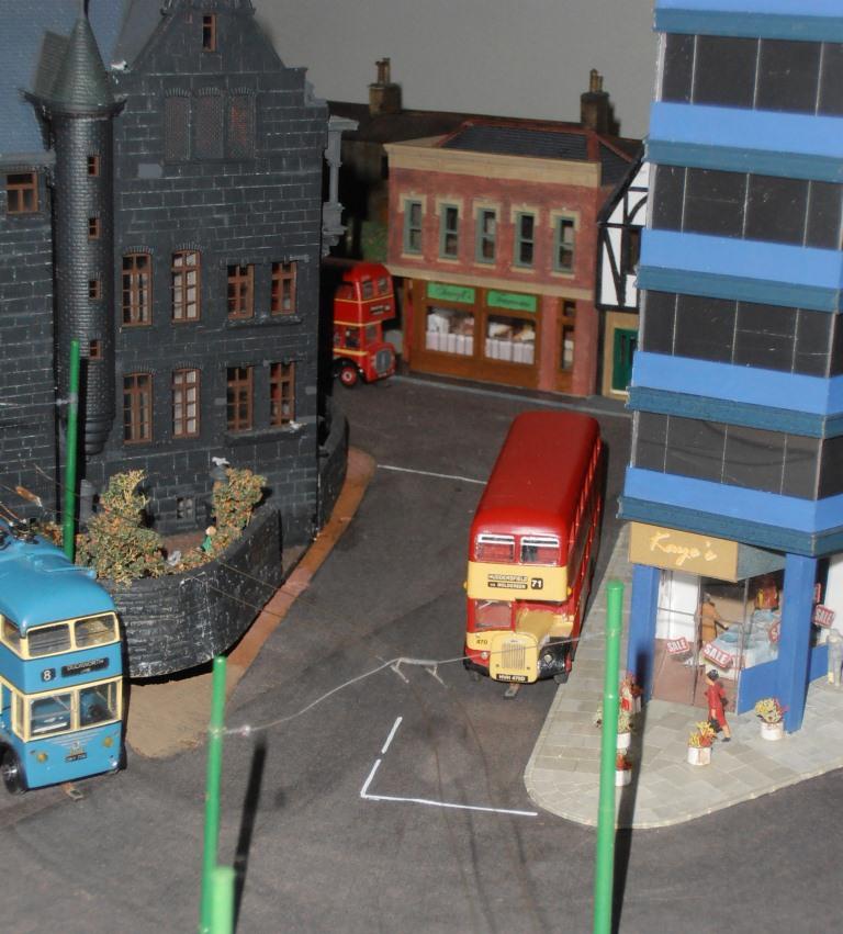
The bridge end of the canal with Huddersfield, Halifax, Bradford and Hebble buses in view. A slow 'up' coal train runs alongside the passing loop while a Transpennine is going the other way. (>>)
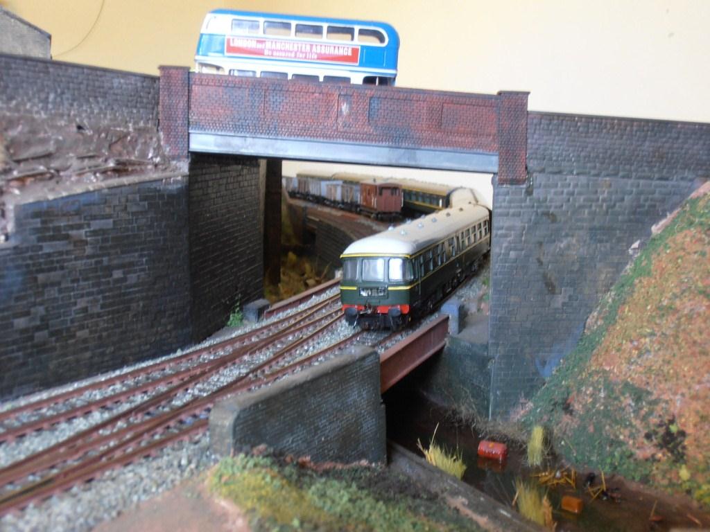
Closer detail of this end of the canal with a Transpennine set thundering through the bridge whilst a Bradford bus passes above.
(>>)
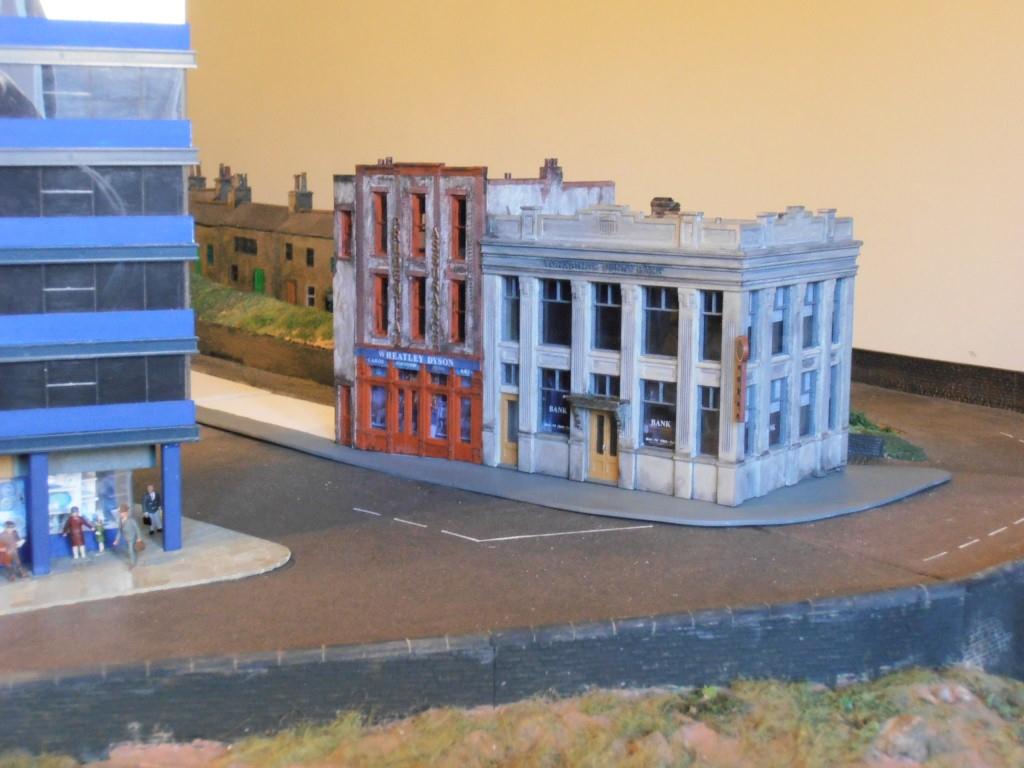
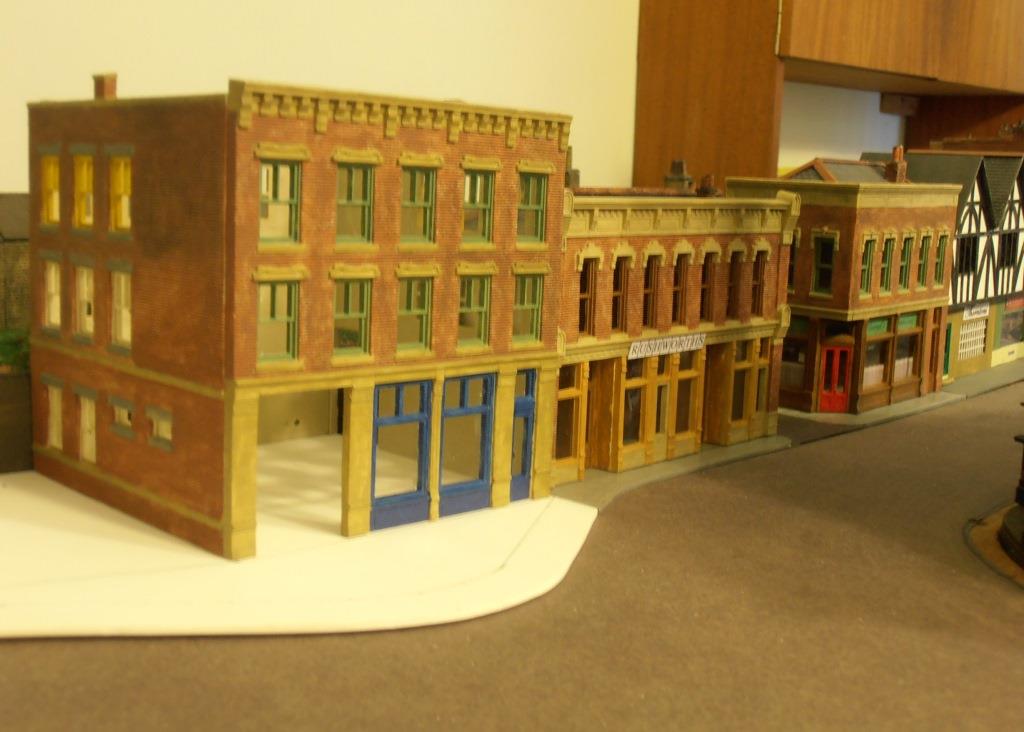
The first building on the main shopping street is a Yorkshire Penny Bank. Next door is a Stationers with Prudential Assurance above. Next to be constructed will be some mock-Tudor shops. (>>)
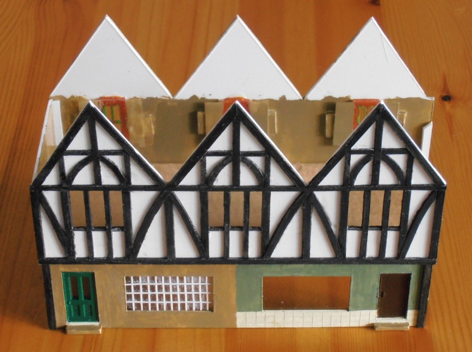
The scratch-built Tudor block completed apart from the roof, and ready to install next to the Stationers. I'm pleased with the result. (>>)
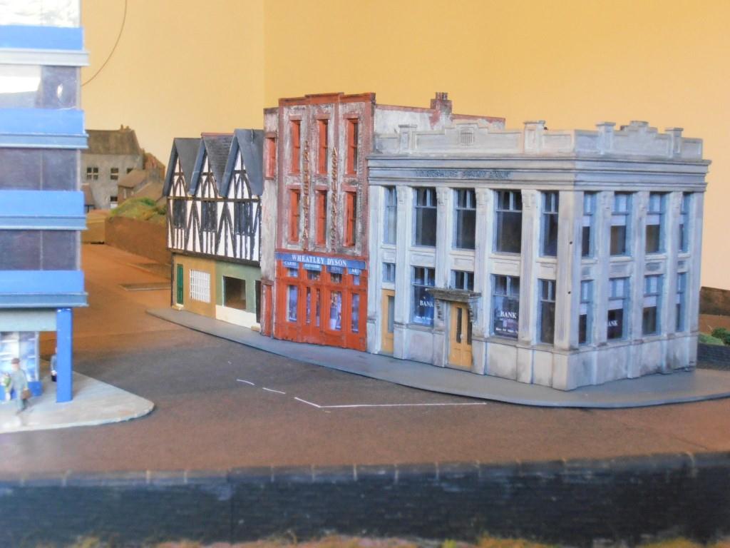
The Tudor shops installed - this is the first of 3 sub-bases finished which will form the main street. (>>)
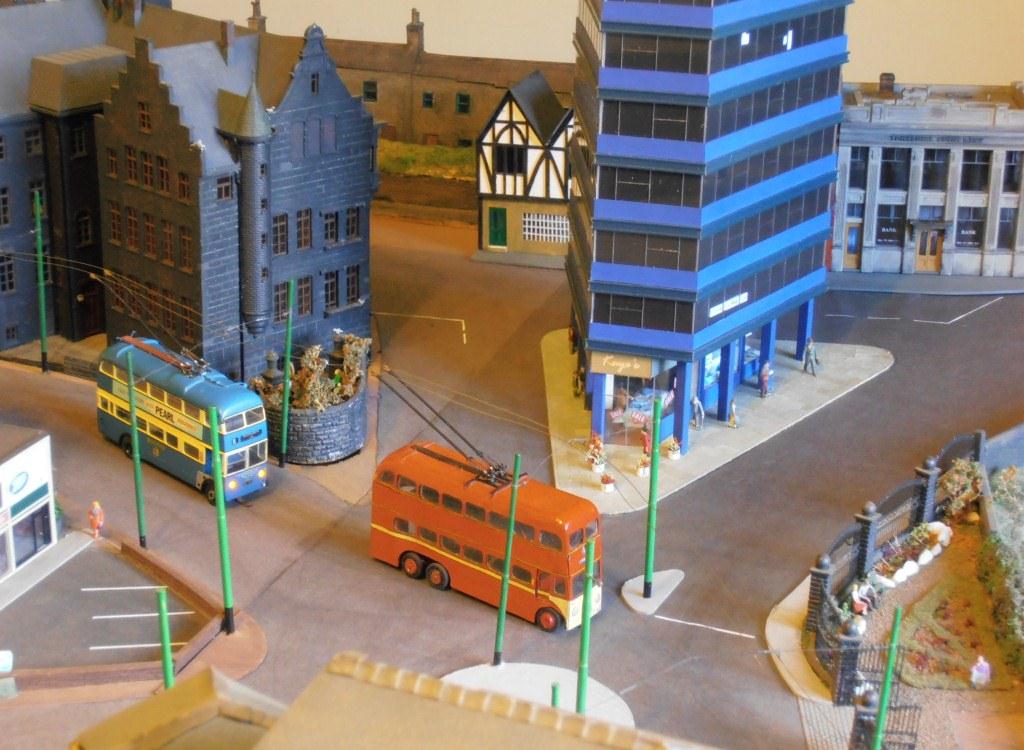
Another view taking in more of the surroundings. Next will be a corner shop, probably a caf�. (>>)
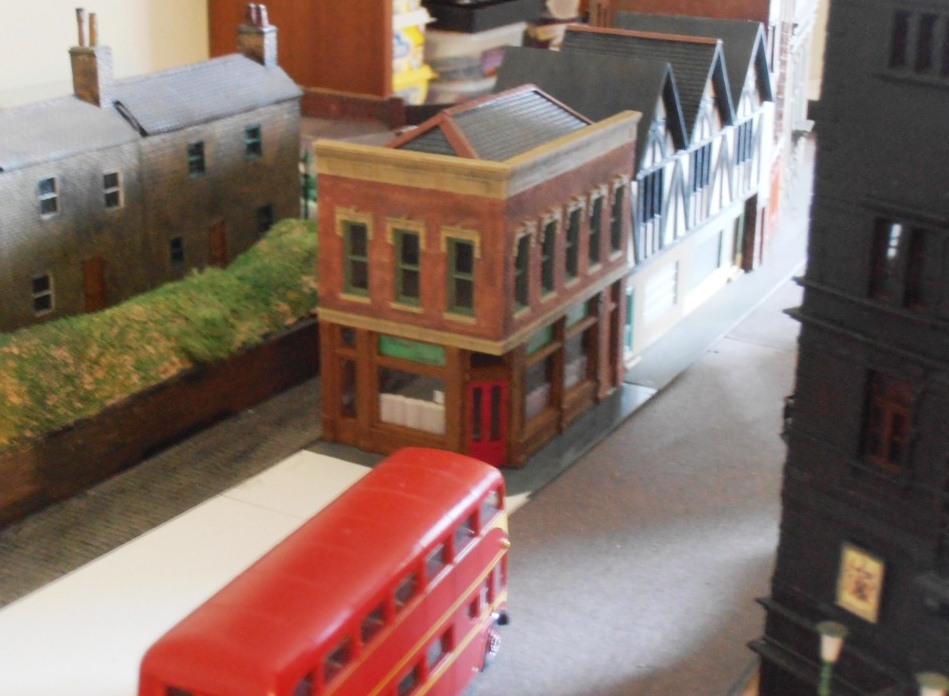
The completed caf�, actually called a tearoom, shown from the other end. (>>)
A front view, looking up the opposite street. (>>)
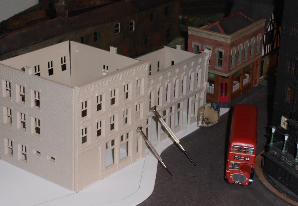
The next two buildings are to be a larger shop and then an arcade (nearest one). These are positioned to check for fit before painting and assembling. The larger shop will complete the second sub-base and the arcade will start the third and last one.
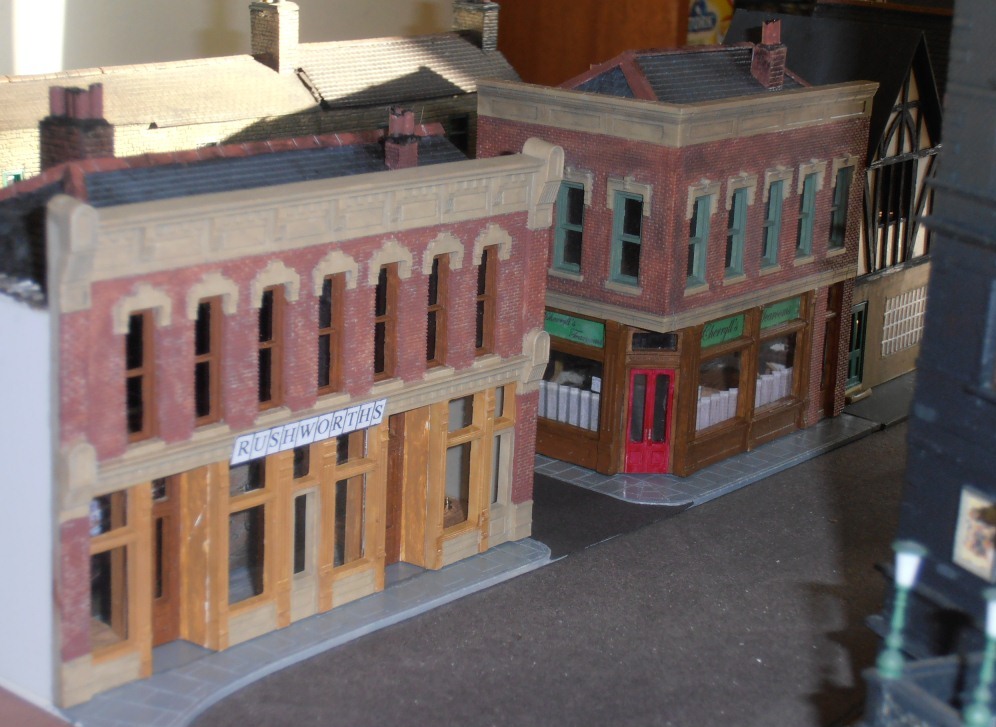
The large shop completed. This has become 'Rushworths' which
was a large Huddersfield Department Store at the time. A narrow lane between
it and the tearooms provides access to the rear of the shops.
(>>)
A view along the rear of the shops at this stage.
The next building - a shopping Arcade - is taking shape and will be followed by an end shop.

The end shop now finished - note this one has closed down and therefore empty. Next door will be a partially demolished building. (>>)
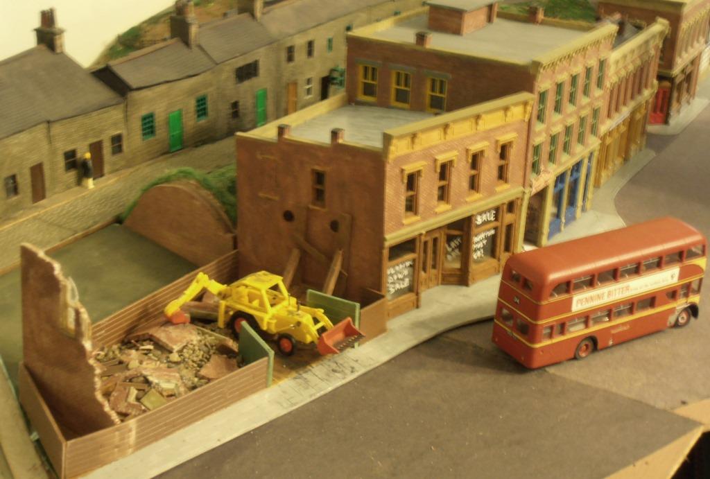
The demolition site completes the last section. Part of the unfinished bit of scenery can be seen behind. (>>)
The remaining plasterwork for the scenery on both sides of the lane is finished off and Autumnal foliage and pavements added. (>>)
The bottom corner near the canal has been walled to form the
enclosure for Walkers Nurseries.
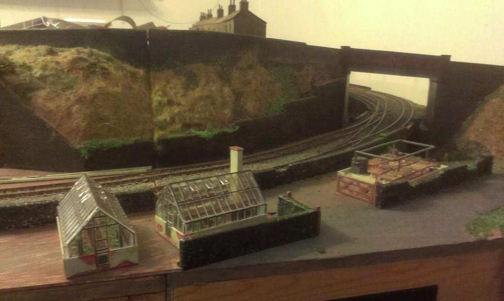
The walls weathered and Greenhouses constructed. One of the smaller ones will be used on a housing development elsewhere.
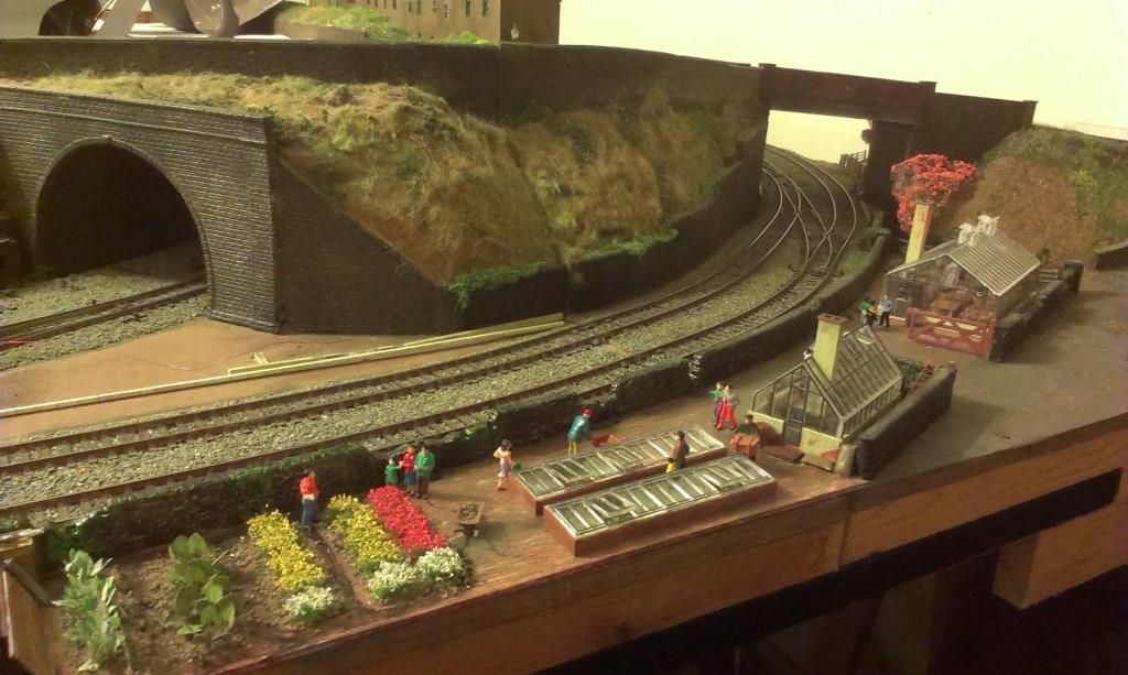
The finished corner, which makes quite a nice busy scene. The railway cable troughing has since been finished in this area. (>>)
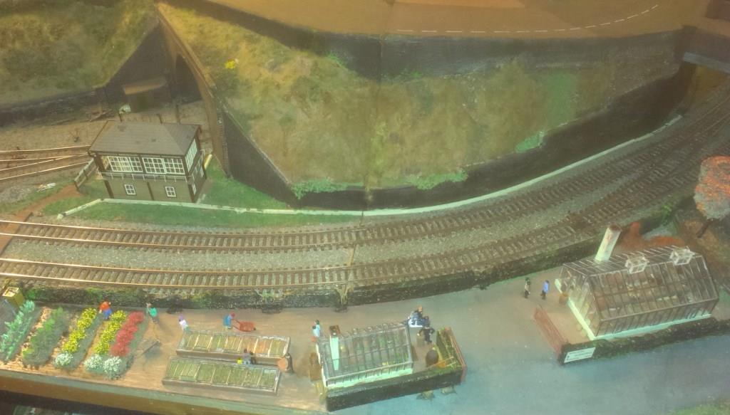
The area with the signal box and its associated cable trunking in place. (>>)